Preliminary Mercury 3000Si Dual Axis Averager ™ Motion Control Feedback Using Averaging of Two Sensors Installation Manual and Reference Guide Manual No.
Introduction MicroE Systems was founded to advance encoder technology to a level never before achieved. Our objective was to design encoder systems that would be small enough to fit into densely packed OEM equipment designs, affordable enough for cost-sensitive applications and easy enough to enable installation, setup and alignment by assemblers with little training. We are pleased to say that all of these goals have been realized with the introduction of the Mercury family of encoders.
Table Of Contents SYSTEM ILLUSTRATION Encoder with Linear scale Encoder with Rotary scale INSTALLATION INSTRUCTIONS Encoder System Mounting - Linear Encoder System Alignment - Linear Centering the Index & Calibration - Linear Encoder System Mounting - Rotary Encoder System Alignment - Rotary Centering the Index & Calibration - Rotary PAGE 2 3 4 5 5 6 7 7 REFERENCE SECTION Installation of Linear Scales Grounding Instructions Recommendations for Power Customer Interface Cable Requirements Serial Output Spec
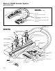
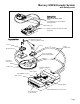
Mercury 3000Si Encoder System with Linear scale System View Shown with linear scale Glass scale (shown mounted on a linear slide) Sensors (shown attached on a linear slide base with mounting brackets) Dual Axis/SmartPrecision electronics module (interpolator) Double shielded cables Expanded View Mounting screws & flat washers (2 needed per screw) Sensor 2 Sensor mounting holes (2) Optional sensor benching pins (3) Sensor 1 Typical user-supplied sensor mounting brackets End locator pin Cover: Sensor ca
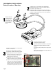
Mercury 3000Si Encoder System with Rotary scale System View Shown with Rotary scale Sensors (shown attached to a customer-supplied mounting brackets) Rotary scale Dual Axis/SmartPrecision electronics module (interpolator) Expanded View Mounting screws & flat washers (2 needed per screw) Sensor 1 Sensor 2 Double shielded cable Mounting hole (2) Typical user-supplied sensor mounting bracket Top reflective rotary scale Rotary scale PowerPower/Calibration Sensor 2 Signal - Sensor 2 Power/Calibration
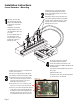
Installation Instructions Linear Encoders - Mounting 2 1 Attach the scale to the base slide. Reference the preferred datum on the interface drawing for either end or center index orientation. Install the sensors on your mounting surfaces referencing the appropriate datum surface as shown on the interface drawing. Use 2 washers per mounting screw. Benching pins may be used to locate each sensor if the system mechanical tolerances are adequate.
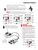
Installation Instructions Linear Encoders - Alignment If benching dimensions cannot be provided, proper sensor alignment may require minor adjustments to each sensor’s position with respect to the scale. This can be performed easily using the LED alignment indicators, as illustrated below. IMPORTANT: Confirm that the Proper Alignment LED blinks when passing over the index. If not, readjust the sensor in the Y direction and repeat the above procedure.
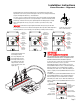
Installation Instructions Rotary Encoders - Mounting 2 1 Install the sensors on your mounting surface referencing the appropriate datum surface as shown on the interface drawing. Use 2 washers per mounting screw. Benching pins may be used to locate each sensor if the system mechanical tolerances are adequate. See data sheet for alignment tolerances, or keep mounting screws loose for sensor alignment if benching pins are not used. Attach your hub/scale assembly to the rotary device.
Installation Instructions Rotary Encoders - Alignment If benching dimensions cannot be provided, proper sensor alignment may require minor adjustments to each sensor’s position with respect to the scale. This can be performed easily using the LED alignment indicators, as illustrated below. IMPORTANT: Confirm that the Proper Alignment LED blinks when passing over the index. If not, readjust the sensor in the Y direction and repeat the above procedure.
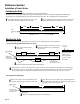
Reference Section Installation of Linear Scales Positioning the Scale Note: Before beginning mounting procedure, use talc-free gloves or finger cots to handle the scales. "Benching" the scale to the system means aligning the scale by means of benching pins. Pin locations are described on the appropriate interface drawing. Two benching pins are recommended on the long side of the scale and one at the end as shown . This is marked datum A on the interface drawing. the benching pins in from either end.
Reference Section Grounding Instructions for Mercury 3000Si Dual Axis Encoder Systems For Mercury 3000Si Dual Axis Averager encoder systems to operate reliably, it is essential that the sensor and cable shield are grounded properly according to the following instructions. The diagrams below show how to make the connections when the encoder's connector is plugged into the customer's controller chassis.
Customer Interface Cable Requirements Customer cables that interface to Mercury series encoders must have the following characteristics: • Twisted pair signal wiring. • Characteristic impedance of 100-120 ohms. • Sufficient wire gauge to meet the minimum voltage requirement at the encoder, for example 24AWG gauge wire for a 2m length cable. Examples of acceptable cables with 24 AWG gauge wire and 5 twisted pairs are Belden 9832, 8105 or other manufacturer’s equivalents.
Serial Output Specification Introduction Historically, the method of choice for many optical position feedback systems has been A quad B (Quadrature) output. The limitation of this method is output speed, especially when the interpolation level is high. When the optical sensor speed and/or the interpolation multiplier is set high, the Quadrature output frequencies will be extremely high and out of the range of the Quadrature counters of most standard motion controllers.
Serial Output Specification Index Processing A unique physical position is referenced on all gratings and is called an index position. The value of this position is determined during an index capture routine initiated by a button press or the SmartPrecision Software and is permanently stored for use after power cycling. The index value has the same resolution as the interpolated position. The M3000SiDAA has four modes of operation that use the index position to generate a physical reference position.
Optional SmartPrecision Software Installation Instructions Hardware Requirements: SmartPrecision Software for M3000SiDAA requires a PC with the following minimum specifications: · Windows 2000 or XP operating systems · 300MHz · 32Mb RAM · 1024 x 768 or higher screen resolution with High Color (16 bit color) · 20Mb free disk space · One USB port (Version 1.
Configuration and Setup - SmartPrecision Software The M3000SiDAA interpolator module can be configured quickly and easily using the SmartPrecision Software. The M3000SiDAA interpolator will accept input from two separate encoders. The M3000SiDAA has three output channels. These can be configured to output the following: Channel 1, Channel 2, Average ((Ch1+Ch2)/2), and/or Difference (Ch1-Ch2). The main screen shows Encoder Position, Signal Level, Alarm Status, Data Plots, and Setup.
M3000SiDAA Configuration 5 1 6 9 7 10 8 11 2 3 4 Configurations screen 1 2 Channel for Average Index: Selects the input channel index that will be used for the Averaged output. Example shown: Index for Channel 1 selected Output Channels [1 - 2 - 3]: The Mercury Dual Axis Averager uses two sensors as inputs and has three output channels. Each sensor's signal is processed for accuracy enhancement and interpolated.
M3000SiDAA Configuration 3 4 5 6 7 8 Channel 1 & 2 Calibration Settings If two separate axes are used the recommended setting is "Calibrate signal and center index". For applications where two sensors are used on the same axis or if the index mark is not in the range of motion for one of the encoders, the "Calibrate signal only" will allow proper calibration of the signal. Fringe Counter Size The M3000SiDAA allows the user to configure the serial word to increase sampling rate.
Display Setting Dual Axis Software Display Settings The Status Display in the center of the screen gives the user a snapshot of the interpolator configuration as well as Index position indication. The indicator light on the SmartPrecision software mimics the LED on the M3000SiDAA. The indicator will be green as long as the encoder is within the index window.
Calibration - SmartPrecision Software Confirm Calibration screen Calibration should be performed only after each of the encoders is aligned properly. Calibration can be initiated by either the Calibrate button using Smart Signal Software or through the recessed push button switch in the M3000SiDAA. To calibrate Channel 1: Through Software: Select "CALIBRATE SIGNAL on INPUT CHANNEL 1" Through Hardware: Push the recessed button once.
Calibrate - SmartPrecision Software Encoder Signal Data Plot showing pre-porcessed and processed data. The Encoder Signal Graph will plot the encoder signal for Channel 1 or Channel 2. The M3000SiDAA has a USB interface which allows very fast data collection and plotting. The number of data points to be plotted on the graph at one time can be changed using the "Plot Settings" button. The processed (Green) and/or the pre-processed (Red) signals can be shown on the graph.
System Specifications Operating and Electrical Specifications Maximum Power Supply: Operating Temperature: Storage Temperature: Humidity: 5V+/-5% @ 550mA (including two sensors) 0 to 70 degrees C -30 to 80 degrees C 10 to 90% RH non-condensing M3000SiDAA Output Connector Pinout (DB25 ) PIN 1 2 3 4 5 6 7 8 9 10 11 12 13 14 15 16 17 18 19 20 21 22 23 24 25 Page 20 Function Serial Data Output 1+ Serial Data Output 1Chip Select Input 1+ Chip Select Input 1Serial Clock Input 1+ Serial Clock Input 1Serial Da
Serial Output Specification The interface to the M3000SiDAA Interpolator uses the following signals to implement serial communication, n_spiEnable (n_CS), spiDataOut (SDO), spiClockIn (SCK), and optionally spiClockOut (SCF). Each signal is differential and RS-422 compatible.
Serial Output Specification Symbol tspiH tspiL tCSC tCSD tV tCCS tCS Parameter Minimum spiClock High Time 50 spiClock Low Time 50 n_spiEnable to spiClock 0 n_spiEnable to DataValid spiClock to Data Valid spiClock to n_spiEnable 0 n_spiEnable High 50 Typical 80 80 All timing are specified assuming no propagation delay from user's electronics and cabling.
Operational Modes: Trigger Approach Timing Diagram The Trigger Approach can be used in applications where synchronization of the position data to an event is required. Often, this mode is used when a fixed latency between a clock signal and the sampled position data is required. The customer can choose this mode of operation by using the optional SmartPrecision Software. In this mode, triggering is controlled by the n_spiEnable signal.
Serial Output Specification Serial Data Format 8bit status form at 0 28bit Position W ord form at 0 3 3 3 3 3 3 2 2 2 2 2 2 2 2 2 2 1 1 1 1 1 1 1 1 1 1 9 8 7 6 5 4 3 2 1 0 5 4 3 2 1 0 9 8 7 6 5 4 3 2 1 0 9 8 7 6 5 4 3 2 1 0 7 6 5 4 3 2 1 0 28 bit P osition W ord form at 1 7 6 5 4 3 2 1 0 8bit status form at 1 Troubleshooting Problem The Power/Calibration indicator will not come on. Solution • Make sure that the SmartPrecision electronics’ 25-pin HD connector is fully seated and connected.
Cleaning scales General Particle Removal Blow off the contamination with nitrogen, clean air, or a similar gas. Contamination Removal Use a lint-free cleanroom wipe or cotton swab dampened with isopropyl alcohol or acetone only. Handle the scale by the edges. Do not scrub the scale. Contact MicroE Systems Thank you for purchasing a MicroE Systems product. You should expect the highest level of quality and support from MicroE.