
Datasheet


KSZ8895MQX/RQX/FQX/MLX
DS00002246A-page 18 2016 Microchip Technology Inc.
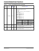
83 SMRXD0 IPD/O
Switch MII/RMII receive bit 0.
Strap option: LED mode PD (default) = mode 0; PU = mode 1. See
“Register 11.”
— Mode 0 Mode 1
LEDx_2 Link/Activity 100Link/Activity
LEDx_1 Full-Duplex/Col 10Link/Activity
LEDx_0 Speed Full-Duplex
86 SCONF1 IPD
Pin 91,86,87 are dual MII/RMII configuration pins for the Port 5 MAC
5 MII/RMII and PHY [5] MII/RMII. SW5-MII supports both MAC mode
and PHY modes. P5-MII supports PHY mode only. See pins configu-
ration below.
Pins
[91, 86, 87]
Port 5 Switch MAC5
SW5- MII/RMII
Port 5 PHY5 P5-MII/RMII
000 Disable, Otri Disable, Otri
001 PHY Mode MII, or RMII Disable, Otri
010 MAC Mode MII, or RMII Disable, Otri
011 PHY Mode SNI Disable, Otri
100 Disable (default) Disable (default)
101 PHY Mode MII, or RMII P5-MII/RMII
110 MAC Mode MII, or RMII P5-MII/RMII
111 PHY Mode SNI P5-MII/RMII
87 SCONF0 IPD Dual MII/RMII configuration pin. See Pin 86 description.
90 LED5-2 IPU/O
LED5 indicator 2.
Strap option: Aging setup. See “Aging” section
PU (default) = aging enable;
PD = aging disable.
91 LED5-1 IPU/O
LED5 indicator 1.
Strap option:
PU (default): enable PHY [5] MII I/F.
PD: Tri-state all PHY [5] MII output. See “Pin 86 SCONF1.”
92 LED5-0 IPU/O
LED5 indicator 0.
Strap option for Port 4 only.
PU (default) = Enable auto-negotiation.
PD = Disable auto-negotiation. Strap to Register76 bit [7].
95 LED4-0 IPU/O
LED indicator 0.
Strap option:
PU (default) = Normal mode.
PD = Energy Detection mode (EDPD mode).
Strap to Register 14 bits [4:3].
98 LED3-0 IPU/O
LED3 indicator 0.
Strap option:
PU (default) = Select I/O current drive strength (8 mA);
PD = Select I/O current drive strength (12 mA).
Strap to Register132 bit [7:6].
TABLE 2-2: STRAP-IN OPTIONS - KSZ8895MQX/RQX/FQX/MLX (CONTINUED)
Pin Number Pin Name
Type,
Note 2-3
Description, Note 2-4