
Datasheet


KSZ8895MQX/RQX/FQX/MLX
DS00002246A-page 16 2016 Microchip Technology Inc.
Note 2-1 P = Power supply.
I = Input.
O = Output.
I/O = Bidirectional.
GND = Ground.
IPU = Input with internal pull-up.
IPD = Input with internal pull-down.
IPD/O = Input with internal pull-down during reset, output pin otherwise.
OTRI = Output tri-stated.
Note 2-2 NC = Do not connect to PCB.
PU = Strap pin pull-up.
PD = Strap pull-down.
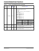
123 NC NC — No connection. Leave NC pin floating.
124 NC NC — No connection. Leave NC pin floating.
125 LDO_O P —
LDO_O pin connect to gate pin of MOSFET if using the internal
1.2V LDO controller.
LDO_O pin will be floating if using an external 1.2V LDO.
Note: When Pin126 voltage is greater than the internal 1.2V LDO
controller enable threshold (1V), the internal 1.2V LDO controller is
enabled and creates a 1.2V output when using an external MOS-
FET.
When Pin126 is pull-down, the internal 1.2V LDO controller is dis-
abled and Pin 125 tri-stated.
126
IN_PWR_-
SEL
I—
A resistor divider: Enable internal 1.2V LDO controller.
Pull-down: Disable internal 1.2V LDO controller by a pull-down
resistor when using an external 1.2V LDO for 1.2V power supply.
Note: A 4 k pull-up and a 2 k pull-down resistors divider network
is recommended if using the internal 1.2V LDO controller and an
external MOSFET for 1.2V power.
A 100 (approximately) resistor between the source and drain pins
on the MOSFET is highly recommended as well.
127 GNDA GND — Analog ground.
128 TEST2 NC — NC for normal operation. Factory test pin.
TABLE 2-1: SIGNALS - KSZ8895MQX/RQX/FQX/MLX (CONTINUED)
Pin
Number
Pin
Name
Type,
Note
2-1
Port Pin Function, Note 2-2