
User Guide

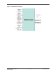


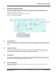

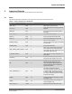

Table Of Contents

2. Inputs and Outputs
This section describes the inputs and the outputs of the H.264 Encoder.
2.1 Ports
The following tables list the description of the input and the output ports of the H.264 Encoder.
Table 2-1. Inputs and Outputs of H.264 Encoder
Signal Name Direction Width Description
DDR_CLK_I Input 1 DDR memory controller clock
PIX_CLK_I Input 1
Input clock with which incoming pixels are
sampled
RESET_N Input 1
Active-low Asynchronous reset signal to
the design
DATA_VALID_I Input 1 Input Pixel data valid signal
DATA_Y_I Input 8 8-bit Luma pixel input in 422 format
DATA_C_I Input 8 8-bit Chroma pixel input in 422 format
FRAME_START_I Input 1
Start of Frame indication
The rising edge of this signal is considered
as frame start.
FRAME_END_I Input 1 End of Frame indication
DDR_FRAME_START_ADDR_I Input 8
DDR memory start address (LSB 24-bits
are 0) to store the reconstructed frame.
The H.264 IP will store 4 frames and it will
use 64 MB of DDR memory.
I_FRAME_FORCE_I Input 1
User can force to I frame at anytime. It is
pulse signal.
PCOUNT_I Input 8
Number of P frames per every I frame
422 format value ranges from 0 to 255.
QP Input 6
Quality factor for H.264 quantization
422 fornat value ranges from 0 to 51
where 0 represents highest quality and
lowest compression and 51 represents
highest compression.
SKIP_THRESHOLD_I Input 12
Threshold for skip block decision
This value represents the SAD value of 16
x 16 Macro block for skipping. The range
is from 0 to 1024, with a typical value of
512. Higher threshold produces more skip
blocks and low quality.
VRES_I Input 16
Vertical resolution of input image. It must
be multiple of 16.
HRES_I Input 16
Horizontal resolution of input image. It
must be multiple of 16.
DATA_VALID_O Output 1 Signal denoting encoded data is valid.
Inputs and Outputs
© 2022 Microchip Technology Inc.
and its subsidiaries
User Guide
DS50003366B-page 7