
Datasheet
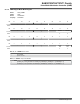

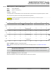


51.7.40 PWM Channel Mode Register
Name: PWM_CMRx
Offset: 0x0200 + x*0x20 [x=0..3]
Reset: 0x00000000
Property: Read/Write
This register can only be written if bits WPSWS2 and WPHWS2 are cleared in the PWM W
rite Protection Status
Register.
Bit 31 30 29 28 27 26 25 24
Access
Reset
Bit 23 22 21 20 19 18 17 16
PPM DTLI DTHI DTE
Access
R/W R/W R/W R/W
Reset 0 0 0 0
Bit 15 14 13 12 11 10 9 8
TCTS DPOLI UPDS CES CPOL CALG
Access
R/W R/W R/W R/W R/W R/W
Reset 0 0 0 0 0 0
Bit 7 6 5 4 3 2 1 0
CPRE[3:0]
Access
R/W R/W R/W R/W
Reset 0 0 0 0
Bit 19 – PPM Push-Pull Mode
The Push-Pull mode is enabled for channel x.
Value Description
0
The Push-Pull mode is disabled for channel x.
1
The Push-Pull mode is enabled for channel x.
Bit 18 – DTLI Dead-T
ime PWMLx Output Inverted
Value Description
0
The dead-time PWMLx output is not inverted.
1
The dead-time PWMLx output is inverted.
Bit 17 – DTHI Dead-T
ime PWMHx Output Inverted
Value Description
0
The dead-time PWMHx output is not inverted.
1
The dead-time PWMHx output is inverted.
Bit 16 – DTE Dead-T
ime Generator Enable
Value Description
0
The dead-time generator is disabled.
1
The dead-time generator is enabled.
Bit 13 – TCTS T
imer Counter Trigger Selection
Value Description
0
The comparator of the channel x (OCx) is used as the trigger source for the Timer Counter (TC).
1
The counter events of the channel x is used as the trigger source for the Timer Counter (TC).
SAM E70/S70/V70/V71 Family
Pulse W
idth Modulation Controller (PWM)
© 2019 Microchip T
echnology Inc.
Datasheet
DS60001527D-page 1639