
Datasheet


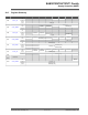

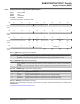
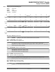


Figure 23-9. Low-power Debouncer (Push-to-Make Switch, Pull-up Resistors)
MCU
WKUP0
WKUP1
RTCOUTx
Pull-up
Resistor
Pull-up
Resistor
GND
GND
GND
Figure 23-10. Low-power Debouncer (Push-to-Break Switch, Pull-down Resistors)
MCU
WKUP0
WKUP1
RTCOUTx
Pull-down
Resistors
GND GND
GND
The debouncing period duration is configurable. The period is set for all debouncers (i.e., the duration cannot be
adjusted for each debouncer). The number of successive identical samples to wake up the system can be configured
from 2 up to 8 in SUPC_WUMR.LPDBC. The period of time between two samples can be configured by programming
R
TC_MR.TPERIOD. Power parameters can be adjusted by modifying the period of time in RTC_MR.THIGH.
The wakeup polarity of the inputs can be independently configured by writing SUPC_WUMR.WKUPT0 and/ or
SUPC_WUMR.WKUPT1.
In order to determine which wakeup/tamper pin triggers the system wakeup, a status flag is associated for each low-
power debouncer. These flags are read in SUPC_SR.
A debounce event (tamper detection) can perform an immediate clear (0 delay) on the first half the general-purpose
backup registers (GPBR). SUPC_WUMR.LPDBCCLR bit must be set.
Note that it is not mandatory to use the RTCOUTx pin when using the WKUP0/WKUP1 pins as tampering inputs in
any mode. Using the RTCOUTx pin provides a “sampling mode” to further reduce the power consumption of the
tamper detection circuitry. If RTCOUTx is not used, the RTC must be configured to create an internal sampling point
for the debouncer logic. The period of time between two samples can be configured by programming
RTC_MR.TPERIOD.
The following figure illustrates the use of WKUPx without the RTCOUTx pin.
SAM E70/S70/V70/V71 Family
Supply Controller (SUPC)
© 2019 Microchip T
echnology Inc.
Datasheet
DS60001527D-page 162