
Datasheet


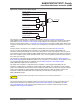


Figure 51-30. External PWM Start Mode: Buck DC/DC Converter
C
IN
C
OUT
L
D
I
L
V
IN
V
OUT
V
REF
PWMH1
PWMH1
V
DC
V
OUT
t
OFF
TRGIN1
TRGEDGE(PWM_ETRG1) = 0
switch to
high load
Time
+ +
Min
imum
t
OFF
Constant
t
ON
51.6.5.3 Cycle-By-Cycle Duty Mode
51.6.5.3.1 Description
Cycle-by-cycle duty mode is selected by programming TRGMODE = 3 in PWM_ETRGx.
In this mode, the PWM frequency is constant and is defined by the CPRD value in the PWM Channel Period
Register.
An external trigger event has no ef
fect on the PWM output if it occurs while the internal PWM counter value is above
the CDTY value of the PWM Channel Duty Cycle Register.
If the internal PWM counter value is below the value of CDTY of the PWM Channel Duty Cycle Register, an external
trigger event makes the PWM output inactive.
The external trigger event can be detected on rising or falling edge according to the TRGEDGE bit in PWM_ETRGx.
SAM E70/S70/V70/V71 Family
Pulse W
idth Modulation Controller (PWM)
© 2019 Microchip T
echnology Inc.
Datasheet
DS60001527D-page 1580