
Datasheet


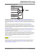


Figure 51-22. Method 3 (UPDM = 2 and PTRM = 1 and PTRCS = 0)
CCNT0
CDTYUPD
0x20
0x40
0x60
UPRCNT
0x0
0x1
0x0
0x1
0x0
0x1
CDTY
UPRUPD
0x1
0x3
CMP0 match
transfer request
WRDY
0x0
0x1
0x2
0x3
0x0
0x1
0x2
UPR
0x1
0x3
0x80
0xA0
0xB0
0x20
0x40
0x60
0x80
0xA0
51.6.2.10 Update Time for Double-Buffering Registers
All channels integrate a double-buffering system in order to prevent an unexpected output waveform while modifying
the period, the spread spectrum value, the polarity, the duty-cycle, the dead-times, the output override, and the
synchronous channels update period.
This double-buffering system comprises the following update registers:
• PWM Sync Channels Update Period Update Register
• PWM Output Selection Set Update Register
• PWM Output Selection Clear Update Register
• PWM Spread Spectrum Update Register
• PWM Channel Duty Cycle Update Register
• PWM Channel Period Update Register
• PWM Channel Dead Time Update Register
• PWM Channel Mode Update Register
When one of these update registers is written to, the write is stored, but the values are updated only at the next PWM
period border. In Left-aligned mode (CALG = 0), the update occurs when the channel counter reaches the period
value CPRD. In Center-aligned mode, the update occurs when the channel counter value is decremented and
reaches the 0 value.
In Center-aligned mode, it is possible to trigger the update of the polarity and the duty-cycle at the next half period
border. This mode concerns the following update registers:
• PWM Channel Duty Cycle Update Register
• PWM Channel Mode Update Register
The update occurs at the first half period following the write of the update register (either when the channel counter
value is incrementing and reaches the period value CPRD, or when the channel counter value is decrementing and
reaches the 0 value). To activate this mode, the user must write a one to the bit UPDS in the PWM Channel Mode
Register.
51.6.3 PWM Comparison Units
The PWM provides 8 independent comparison units able to compare a programmed value with the current value of
the channel 0 counter (which is the channel counter of all synchronous channels, “Synchronous Channels”). These
comparisons are intended to generate pulses on the event lines (used to synchronize ADC, see PWM Event Lines),
to generate software interrupts and to trigger DMA Controller transfer requests for the synchronous channels (see
Method 3: Automatic write of duty-cycle values and automatic trigger of the update).
SAM E70/S70/V70/V71 Family
Pulse W
idth Modulation Controller (PWM)
©
2019 Microchip Technology Inc.
Datasheet
DS60001527D-page 1573