
Datasheet


7. The update of these registers will occur at the beginning of the next PWM period. At this moment the bit
UPDULOCK is reset, go to Step 5. for new values.
8.
If an update of the duty-cycle values and/or the update period is required, check first that write of new update
values is possible by polling the flag WRDY (or by waiting for the corresponding interrupt) in PWM_ISR2.
9. Write registers that need to be updated (PWM_CDTYUPDx, PWM_SCUPUPD).
10. The update of these registers will occur at the next PWM period of the synchronous channels when the
Update Period is elapsed. Go to Step 8. for new values.
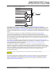
Figure 51-20. Method 2 (UPDM = 1)
CCNT0
CDTYUPD
0x20
0x40
0x60
UPRCNT
0x0
0x1
0x0
0x1
0x0
0x1
CDTY
0x20
0x40
UPRUPD 0x1
0x3
WRDY
0x60
0x0
0x1
0x2
0x3
0x0
0x1
0x2
UPR
0x1
0x3
51.6.2.9.3 Method 3: Automatic write of duty-cycle values and automatic trigger of the update
In this mode, the update of the duty cycle values is made automatically by the DMA Controller. The update of the
period value, the dead-time values and the update period value must be done by writing in their respective update
registers with the processor (respectively PWM_CPRDUPDx, PWM_DTUPDx and PWM_SCUPUPD).
T
o trigger the update of the period value and the dead-time values, the user must use the bit UPDULOCK which
allows to update synchronously (at the same PWM period) the synchronous channels:
• If the bit UPDULOCK is set to ‘1’, the update is done at the next PWM period of the synchronous channels.
• If the UPDULOCK bit is not set to ‘1’, the update is locked and cannot be performed.
After writing the UPDULOCK bit to ‘1’, it is held at this value until the update occurs, then it is read 0.
The update of the duty-cycle values and the update period value is triggered automatically after an update period.
To configure the automatic update, the user must define a value for the Update Period by the field UPR in the
PWM_SCUP register. The PWM controller waits UPR+1 periods of synchronous channels before updating
automatically the duty values and the update period value.
Using the DMA Controller removes processor overhead by reducing its intervention during the transfer. This
significantly reduces the number of clock cycles required for a data transfer, which improves microcontroller
performance.
The DMA Controller must write the duty-cycle values in the synchronous channels index order. For example if the
channels 0, 1 and 3 are synchronous channels, the DMA Controller must write the duty-cycle of the channel 0 first,
then the duty-cycle of the channel 1, and finally the duty-cycle of the channel 3.
The status of the DMA Controller transfer is reported in PWM_ISR2 by the following flags:
• WRDY: this flag is set to ‘1’ when the PWM Controller is ready to receive new duty-cycle values and a new
update period value. It is reset to ‘0’ when PWM_ISR2 is read. The user can choose to synchronize the WRDY
flag and the DMA Controller transfer request with a comparison match (see PWM Comparison Units), by the
fields PTRM and PTRCS in the PWM_SCM register.
•
SAM E70/S70/V70/V71 Family
Pulse W
idth Modulation Controller (PWM)
©
2019 Microchip Technology Inc.
Datasheet
DS60001527D-page 1571