
Datasheet


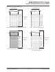


Figure 22-11. Programming Bytes in the Flash
32 bits wide
FF FF FF FF
FF
FF FF FF
FF FF FF FF
FF FF FF FF
0xX00
0xX04
0xX08
0xX0C
0xX10
0xX14
0xX18
0xX1C
address space
for
Page N
Step 1: Flash array after programming first byte (0xAA)
128-bit used at address 0xX00 (write latch buffer + WP)
FF FF FF FF
xx xx xx xx
xx xx xx AA
32 bits wide
0xX00
0xX04
0xX08
0xX0C
0xX10
0xX14
0xX18
0xX1C
FF FF FF FF
xx xx xx xx
xx xx xx AA
Step 2: Flash array after programming second byte (0x55)
128-bit used at address 0xX10 (write latch buffer + WP)
xx xx xx xx
xx xx xx xx
xx xx xx xx
xx xx xx 55
xx xx xx xx
xx xx xx xx
xx xx xx xx
xx xx xx xx
Note: The byte location shown here is for example only, it can be any byte location within a 64-bit word
4 x 32 bits =
1 Flash word
4 x 32 bits =
1 Flash word
22.4.3.3 Erase Commands
Erase commands are allowed only on unlocked regions. Depending on the Flash memory, several commands can be
used to erase the Flash:
•
Erase All Memory (EA): All memory is erased. The processor must not fetch code from the Flash memory.
• Erase Pages (EPA): 4, 8, 16, or 32 pages are erased in the Flash sector selected. The first page to be erased is
specified in the FARG[15:2] field of the EEFC_FCR. The first page number must be a multiple of 8, 16, or 32
depending on the number of pages to erase simultaneously.
• Erase Sector (ES): A full memory sector is erased. Sector size depends on the Flash memory.
EEFC_FCR.FARG must be set with a page number that is in the sector to be erased.
Note: If one sub-sector is locked within the first sector, the Erase Sector (ES) command cannot be processed on
non-locked sub-sectors of the first sector. All the lock bits of the first sector must be cleared prior to issuing an ES
command on the first sector. After the ES command has been issued, the first sector lock bits must be reverted to the
state before clearing them.
If the processor is fetching code from the Flash memory while the EPA or ES command is being executed, the
processor accesses are stalled until the EPA command is completed. To avoid stalling the processor, the code can be
run out of internal SRAM.
The following are the erase sequence:
1. Erase starts immediately one of the erase commands and the FARG field are written in EEFC_FCR.
For the EPA command, the two lowest bits of the FARG field define the number of pages to be erased
(FARG[1:0]), see table below.
Table 22-3. EEFC_FCR.FARG Field for EPA Command
FARG[1:0] Number of pages to be erased with EPA command
0 4 pages (only valid for small 8-KB sectors)
1 8 pages (only valid for small 8-KB sectors)
2 16 pages
SAM E70/S70/V70/V71 Family
Enhanced Embedded Flash Controller (EEFC)
© 2019 Microchip T
echnology Inc.
Datasheet
DS60001527D-page 139