
Datasheet


SAM3X / SAM3A [DATASHEET]
Atmel-11057C-ATARM-SAM3X-SAM3A-Datasheet_23-Mar-15
1450
Note: 1. “rfo” indicates changes requested during document review and approval loop.
Doc. Rev.
11057B Comments
Change
Request
Ref.
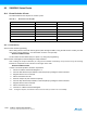
SDRAM and 217-pin package information removed only from Section “Features”, Section 1.1 “Configuration
Summary” (introduction) and Section 48. “Ordering Information”.
8251
“Write protected Registers” added to Section “Features”.8213
Section “Features”, Section 1.1 “Configuration Summary” (introduction) updated.
Figure 2-3 ”SAM3X4/8E (144 pins) Block Diagram” updated.
Section 1.1 “Configuration Summary”, added a note “The SAM3X-EK evaluation kit for the SAM3X and SAM3A
series is mounted with a SAM3X8H in a LFBGA217 package. This device is not commercially available.”
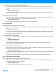
Section 46. “Mechanical Characteristics”, deleted Figure 46-5 “217-ball LFBGA Package Drawing” and the
corresponding tables (46-15, 46-16, 46-17, and 46-18).
Section 48. “Ordering Information” updated, ATSAM3X8H-CU information and the note deleted in Table 48-1.
8316
Added a note explaining that SAM3X8H is not commercially available, and replaced “217-pin” / “217-pin
SAM3X” by “217-pin SAM3X8H” in Figure 2-4, Section 5. “Power Considerations”, Section 7.2.1 “Internal
SRAM”, Section 7.3 “External Memories”, Section 7.3.5 “SDR-SDRAM Controller (217-pin SAM3X8H(l) only)”,
Section 9.3 “Peripheral Signal Multiplexing on I/O Lines”, Section 22.2 “Embedded Characteristics” (DMAC),
Section 23.2 “Embedded Characteristics” (External Memory Bus), Section 26.2 “Embedded Characteristics”
(PDC), Section 29.2 “Embedded Characteristics” (CHIPID), Section 31.2 “Embedded Characteristics” (PIO),
and Section 49.1 “Errata Revision A Parts”.
Section 7. “Memories” added to the Overview.
8318
Section 1.1 “Configuration Summary”, removed SAM3X8H information from Table 1-1 on page 3 and added a
note explaining that SAM3X8H is not commercially available.
Removed entirely Section 4.3 SAM3X8H Package and Pinout.
Updated new notes style: changed the color from red to black.
rfo
(1)
Fixed incorrectly displayed figures (due to Adobe Illustrator to PDF conversion problem): Figure 5-5 ”Wake-up
Source”, Figure 25-36 ”NAND Flash Controller Timing Engine”, Figure 25-38 ”Program Page Flow Chart”,
Figure 27-2 ”Typical Slow Clock Crystal Oscillator Connection”, Figure 27-3 ”Main Clock Block Diagram”,
Figure 28-1 ”General Clock Block Diagram”, Figure 28-3 ”Master Clock Controller”, Figure 36-1 ”Timer Counter
Block Diagram”, and Figure 38-3 ”Functional View of the Channel Block Diagram”.
rfo
(1)
Doc. Rev.
11057A Comments
Change
Request
Ref.
First Issue