
Datasheet


DRAFT
SAM3X / SAM3A [DATASHEET]
Atmel-11057C-ATARM-SAM3X-SAM3A-Datasheet_23-Mar-15
1388
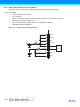
45.3.2.2 Wait Mode
All power supplies are powered
Core Clock and Master Clock Stopped
Current measurement on AMP1, AMP2 and AMP3
All peripheral clocks deactivated
Figure 45-7. Measurement Setup for Wait Mode
Table 45-11 gives current consumption in typical conditions.
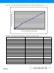
45.3.3 Active Mode Power Consumption
The Active Mode configuration and measurements are defined as follows:
VDDIO = VDDIN = VDDBU= VDDANA = VDUTMI = 3.3V for VDDCORE = 1.8V. VDDOUT not used for
VDDCORE = 1.62V
VDDCORE = 1.8V (internal voltage regulator used)
T
A
= 25°C
CoreMark Algorithm running from Flash Memory or SRAM
All peripheral clocks are deactivated.
Master Clock (MCK) running at various frequencies with PLLA or the fast RC oscillator
Current measurement on AMP1 ( VDDCORE ) and total current on AMP2
VDDUTMI
VDDIO
VDDOUT
VDDCORE
VDDIN
Voltage
Regulator
VDDPLL
VDDANA
3.3V
AMP1
AMP2
VDDBU
AMP3
Table 45-11. Typical Current Consumption in Wait Mode
Conditions
Consumption
Unit
VDDOUT
(AMP1)
Total
(AMP2)
Regulator and Core
(AMP3)
See Figure 45-7
@ 25°C
There is no activity on the I/Os of the device.
18.7 26.6 18.4 µA