
Datasheet


SAM3X / SAM3A [DATASHEET]
Atmel-11057C-ATARM-SAM3X-SAM3A-Datasheet_23-Mar-15
1330
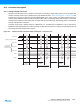
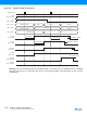
43.6.12 Fault Output
The ADC Controller internal fault output is directly connected to PWM fault input. Fault output may be asserted
according to the configuration of ADC_EMR (Extended Mode Register) and ADC_CWR (Compare Window
Register) and converted values. When the Compare occurs, the ADC fault output generates a pulse of one Master
Clock Cycle to the PWM fault input. This fault line can be enabled or disabled within PWM. Should it be activated
and asserted by the ADC Controller, the PWM outputs are immediately placed in a safe state (pure combinational
path). Note that the ADC fault output connected to the PWM is not the COMPE bit. Thus the Fault Mode (FMOD)
within the PWM configuration must be FMOD = 1.
43.6.13 Write Protection Registers
To prevent any single software error that may corrupt ADC behavior, certain address spaces can be write-
protected by setting the WPEN bit in the “ADC Write Protect Mode Register” (ADC_WPMR).
If a write access to the protected registers is detected, then the WPVS flag in the ADC Write Protect Status
Register (ADC_WPSR) is set and the field WPVSRC indicates in which register the write access has been
attempted.
The WPVS flag is reset by writing the ADC Write Protect Mode Register (ADC_WPMR) with the appropriate
access key, WPKEY.
The protected registers are:
“ADC Mode Register” on page 1333
“ADC Channel Sequence 1 Register” on page 1336
“ADC Channel Sequence 2 Register” on page 1337
“ADC Channel Enable Register” on page 1338
“ADC Channel Disable Register” on page 1339
“ADC Extended Mode Register” on page 1347
“ADC Compare Window Register” on page 1348
“ADC Channel Gain Register” on page 1349
“ADC Channel Offset Register” on page 1350
“ADC Analog Control Register” on page 1352