
Datasheet


SAM3X / SAM3A [DATASHEET]
Atmel-11057C-ATARM-SAM3X-SAM3A-Datasheet_23-Mar-15
1326
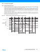
order of channels and can program up to 16 conversions by sequence. The user is totally free to create a personal
sequence, by writing channel numbers in ADC_SEQR1 and ADC_SEQR2. Not only can channel numbers be
written in any sequence, channel numbers can be repeated several times. Only enabled sequence bitfields are
converted, consequently to program a 15-conversion sequence, the user can simply put a disable in
ADC_CHSR[15], thus disabling the 16THCH field of ADC_SEQR2.
If all ADC channels (i.e. 16) are used on an application board, there is no restriction of usage of the user sequence.
But as soon as some ADC channels are not enabled for conversion but rather used as pure digital inputs, the
respective indexes of these channels cannot be used in the user sequence fields (ADC_SEQR1, ADC_SEQR2
bitfields). For example, if channel 4 is disabled (ADC_CSR[4] = 0), ADC_SEQR1, ADC_SEQR2 register bitfields
USCH1 up to USCH16 must not contain the value 4. Thus the length of the user sequence may be limited by this
behavior.
As an example, if only 4 channels over 16 (CH0 up to CH3) are selected for ADC conversions, the user sequence
length cannot exceed 4 channels. Each trigger event may launch up to 4 successive conversions of any
combination of channels 0 up to 3 but no more (i.e. in this case the sequence CH0, CH0, CH1, CH1, CH1 is
impossible).
A sequence that repeats several times the same channel requires more enabled channels than channels actually
used for conversion. For example, a sequence like CH0, CH0, CH1, CH1 requires 4 enabled channels (4 free
channels on application boards) whereas only CH0, CH1 are really converted.
Note: The reference voltage pins always remain connected in normal mode as in sleep mode.
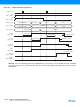
43.6.7 Comparison Window
The ADC Controller features automatic comparison functions. It compares converted values to a low threshold or a
high threshold or both, according to the CMPMODE function chosen in the Extended Mode Register (ADC_EMR).
The comparison can be done on all channels or only on the channel specified in CMPSEL field of ADC_EMR. To
compare all channels the CMP_ALL parameter of ADC_EMR should be set.
Moreover a filtering option can be set by writing the number of consecutive comparison errors needed to raise the
flag. This number can be written and read in the CMPFILTER field of ADC_EMR.
The flag can be read on the COMPE bit of the Interrupt Status Register (ADC_ISR) and can trigger an interrupt.
The High Threshold and the Low Threshold can be read/write in the Comparison Window Register (ADC_CWR).
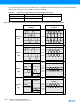
43.6.8 Differential Inputs
The ADC can be used either as a single ended ADC (DIFF bit equal to 0) or as a fully differential ADC (DIFF bit
equal to 1) as shown in Figure 43-6. By default, after a reset, the ADC is in single ended mode.
If ANACH is set in ADC_MR the ADC can apply a different mode on each channel. Otherwise the parameters of
CH0 are applied to all channels.
The same inputs are used in single ended or differential mode.
In single ended mode, inputs are managed by a 16:1 channels analog multiplexer. In the fully differential mode,
inputs are managed by an 8:1 channels analog multiplexer. See Table 43-4 and Table 43-5.
Table 43-4. Input Pins and Channel Number in Single Ended Mode
Input Pins Channel Number
AD0 CH0
AD1 CH1
AD2 CH2
AD3 CH3
AD4 CH4