
Datasheet


1321
SAM3X / SAM3A [DATASHEET]
Atmel-11057C-ATARM-SAM3X-SAM3A-Datasheet_23-Mar-15
43.6 Functional Description
43.6.1 Analog-to-digital Conversion
The ADC uses the ADC Clock to perform conversions. Converting a single analog value to a 12-bit digital data
requires Tracking Clock cycles as defined in the field TRACKTIM of the “ADC Mode Register” on page 1333 and
Transfer Clock cycles as defined in the field TRANSFER of the same register. The ADC Clock frequency is
selected in the PRESCAL field of the Mode Register (ADC_MR). The tracking phase starts during the conversion
of the previous channel. If the tracking time is longer than the conversion time, the tracking phase is extended to
the end of the previous conversion.
The ADC clock range is between MCK/2, if PRESCAL is 0, and MCK/512, if PRESCAL is set to 255 (0xFF).
PRESCAL must be programmed in order to provide an ADC clock frequency according to the parameters given in
the product Electrical Characteristics section.
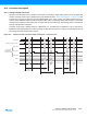
Figure 43-2. Sequence of ADC conversions when Tracking time > Conversion time
ADCClock
LCDR
ADC_ON
Trigger event (Hard or Soft)
ADC_SEL
DRDY
ADC_Start
CH0 CH1
CH0
CH2
CH1
Transfer Period Transfer PeriodStart Up
Time
(and tracking of CH0)
Conversion
of CH0
Conversion
of CH1
Tracking of CH1
Tracking of CH2
Commands
from controller
to analog cell