
Datasheet


1319
SAM3X / SAM3A [DATASHEET]
Atmel-11057C-ATARM-SAM3X-SAM3A-Datasheet_23-Mar-15
43.4 Signal Description
Note: 1. AD15 is not an actual pin but is connected to a temperature sensor.
43.5 Product Dependencies
43.5.1 Power Management
The ADC Controller is not continuously clocked. The programmer must first enable the ADC Controller MCK in the
Power Management Controller (PMC) before using the ADC Controller. However, if the application does not
require ADC operations, the ADC Controller clock can be stopped when not needed and restarted when
necessary. Configuring the ADC Controller does not require the ADC Controller clock to be enabled.
43.5.2 Interrupt Sources
The ADC interrupt line is connected on one of the internal sources of the Interrupt Controller. Using the ADC
interrupt requires the NVIC to be programmed first.
43.5.3 Analog Inputs
The analog input pins can be multiplexed with PIO lines. In this case, the assignment of the ADC input is
automatically done as soon as the corresponding channel is enabled by writing the register ADC_CHER. By
default, after reset, the PIO line is configured as input with its pull-up enabled and the ADC input is connected to
the GND.
43.5.4 Temperature Sensor
The temperature sensor is connected to Channel 15 of the ADC.
The temperature sensor provides an output voltage V
T
that is proportional to absolute temperature (PTAT). To
activate the temperature sensor, TSON bit (ADC_ACR) needs to be set.
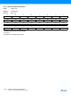
Table 43-1. ADC Pin Description
Pin Name Description
VDDANA Analog power supply
ADVREF Reference voltage
(1)
AD0 - AD15 Analog input channels
ADTRG External trigger
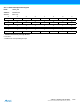
Table 43-2. Peripheral IDs
Instance ID
ADC 37