
Datasheet


SAM9G20
DS60001516A-page 106 2017 Microchip Technology Inc.
16. Watchdog Timer (WDT)
16.1 Overview
The Watchdog Timer can be used to prevent system lock-up if the software becomes trapped in a deadlock. It features a 12-bit down
counter that allows a watchdog period of up to 16 seconds (slow clock at 32.768 kHz). It can generate a general reset or a processor reset
only. In addition, it can be stopped while the processor is in debug mode or idle mode.
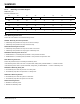
16.2 Block Diagram
Figure 16-1: Watchdog Timer Block Diagram
16.3 Functional Description
The Watchdog Timer can be used to prevent system lock-up if the software becomes trapped in a deadlock. It is supplied with VDDCORE.
It restarts with initial values on processor reset.
The Watchdog is built around a 12-bit down counter, which is loaded with the value defined in the field WDV of the Mode Register
(WDT_MR). The Watchdog Timer uses the Slow Clock divided by 128 to establish the maximum Watchdog period to be 16 seconds (with
a typical Slow Clock of 32.768 kHz).
After a Processor Reset, the value of WDV is 0xFFF, corresponding to the maximum value of the counter with the external reset generation
enabled (field WDRSTEN at 1 after a Backup Reset). This means that a default Watchdog is running at reset, i.e., at power-up. The user
must either disable it (by setting the WDDIS bit in WDT_MR) if he does not expect to use it or must reprogram it to meet the maximum
Watchdog period the application requires.
The Watchdog Mode Register (WDT_MR) can be written only once. Only a processor reset resets it. Writing the WDT_MR reloads the
timer with the newly programmed mode parameters.
=
0
10
set
reset
read WDT_SR
or
reset
wdt_fault
(to Reset Controller)
set
reset
WDFIEN
wdt_int
WDT_MR
SLCK
1/128
12-bit Down
Counter
Current
Value
WDD
WDT_MR
<= WDD
WDV
WDRSTT
WDT_MR
WDT_CR
reload
WDUNF
WDERR
reload
write WDT_MR
WDT_MR
WDRSTEN