
Datasheet


1036
32117D–AVR-01/12
AT32UC3C
33.7.37 Channel Mode Register
Name:
CMR
Access Type: Read/Write
Offset: 0x200 + [ch_num * 0x20]
Reset Value: 0x00000000
This register can only be written if the WPSWS2 and WPHWS2 bits are cleared in ”Write Protect Status Register” on page
1030.
• DTLI: Dead-Time PWMLx Output Inverted
0: The dead-time PWMLx output is not inverted.
1: The dead-time PWMLx output is inverted.
• DTHI: Dead-Time PWMHx Output Inverted
0: The dead-time PWMHx output is not inverted.
1: The dead-time PWMHx output is inverted.
• DTE: Dead-Time Generator Enable
0: The dead-time generator is disabled.
1: The dead-time generator is enabled.
• CES: Counter Event Selection
The CES bit defines when the channel counter event occurs when the period is center aligned (CHIDx in the ”Interrupt Status
Register 1” on page 1005).
CALG=0 (Left Alignment):
0/1: The channel counter event occurs at the end of the PWM period.
CALG=1 (Center Alignment):
0: The channel counter event occurs at the end of the PWM period.
1: The channel counter event occurs at the end of the PWM period and at half the PWM period.
• CPOL: Channel Polarity
0: The OCx output waveform (output from the comparator) starts at a low level.
1: The OCx output waveform (output from the comparator) starts at a high level.
• CALG: Channel Alignment
0: The period is left aligned.
1: The period is center aligned.
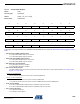
31 30 29 28 27 26 25 24
- -------
23 22 21 20 19 18 17 16
- - - - - DTLI DTHI DTE
15 14 13 12 11 10 9 8
- - - - - CES CPOL CALG
76543210
- - - - CPRE