
Datasheet


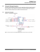


Figure 11-2. Module Drawings – ATWINC15x0-MR210UB (unit = mm)
MODULE TOP VIEW
Metal
Shield
Metal
Shield
PCB
MODULE SIDE VIEW
MODULE BOTTOM VIEW
NOTE: THIS PAD MUST
BE SOLDERED TO GND.
NOT TO SCA LE Rev. 2
11.1 Module Footprint
This section provides the outline drawing for the recommended footprint for the ATWINC15x0-MR210xB
module. It is imperative that the center Ground Pad is provided, with an array of vias to provide for a good
ground and thermal transfer for the ATWINC15x0-MR210xB module.
This footprint is applicable to the ATWINC15x0-MR210xB module devices.
ATWINC15x0
Module Drawing
© 2018 Microchip Technology Inc.
Datasheet
DS70005304C-page 30