
Datasheet


10. Schematic Design Information
This section provides schematic information for reference. Application schematics for SPI are provided in
the following figure. Module design information such as module schematics can be obtained under an
NDA from Microchip. These schematics are applicable to the ATWINC1500-MR210PB, ATWINC1510-
MR210PB, ATWINC1500-MR210UB, and ATWINC1510-MR210UB modules.
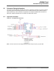
10.1 Application Schematic
Figure 10-1. SPI Application Schematic
Resistors R2-R1 are recommended
As placeholders in case filtering
of noisy signals is required. They
also allow disconnecting of module
For debug purposes.
Note: Add 10uF and 0.01uF decoupling capacitors between the pin 24 (1P3V_TP) and GND.
ATWINC15x0
Schematic Design Information
© 2018 Microchip Technology Inc.
Datasheet
DS70005304C-page 28