
Datasheet


8. Power Consumption
8.1 Description of Device States
The ATWINC15x0-MR210xB has several device states:
• ON_Transmit – Device is actively transmitting an 802.11 signal. Highest output power and nominal
current consumption.
• ON_Receive – Device is actively receiving an 802.11 signal. Lowest sensitivity and nominal current
consumption.
• ON_Doze – Device is ON but is neither transmitting nor receiving
• Power_Down – Device core supply off (Leakage)
• IDLE connect – Device is connected with 1 DTIM beacon interval
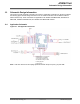
The following pins are used to switch between the ON and Power_Down states:
• CHIP_EN – Device pin (pin #22) used to enable DC/DC Converter
• VDDIO – I/O supply voltage from external supply
In the ON states, VDDIO is on and CHIP_EN is high (at VDDIO voltage level). To switch between
the ON states and Power_Down state CHIP_EN has to change between high and low (GND)
voltage. When VDDIO is off and CHIP_EN is low, the chip is powered off with no leakage (also see
Restrictions for Power States).
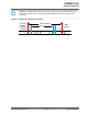
8.2 Current Consumption in Various Device States
Table 8-1. Current Consumption
Device State Code Rate
Output
power, dBm
Current Consumption
1
IVBATT IVDDIO
ON_Transmit
802.11b 1Mbps 17.5 268mA 22mA
802.11b 11Mbps 18.5 264mA 22mA
802.11g 6Mbps 17.5 269mA 22mA
802.11g 54Mbps 16.0 266mA 22mA
802.11n MCS 0 17.0 268mA 22mA
802.11n MCS 7 14.5 265mA 22mA
ON_Receive
802.11b 1Mbps N/A 61mA 22mA
802.11b 11Mbps N/A 61mA 22mA
802.11g 6Mbps N/A 61mA 22mA
802.11g 54Mbps N/A 61mA 22mA
802.11n MCS 0 N/A 61mA 22mA
802.11n MCS 7 N/A 61mA 22mA
ATWINC15x0
Power Consumption
© 2018 Microchip Technology Inc.
Datasheet
DS70005304C-page 23