
Datasheet


4. Board Debugging
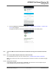
4.1 UART Debug Interface
The Wi-Fi Smart Device Enablement Kit has debug UART pins. The pins are connected to the J9
connector. The user can utilize a USB-to-UART converter to connect the computer, and the board Debug
UART to capture the MCU log.
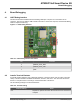
Figure 4-1. UART Debug Interface
Table 4-1. UART Debug Interface Pin Details
Pin Function
3 DEBUG_UART_RXD
5 DEBUG_UART_TXD
7 GND
4.2 Install a Terminal Emulator
A terminal emulator helps the user to diagnose problems or verify the device code is running. There are
variety of terminal emulators available for Windows
®
, macOS
®
, and Linux
®
. The user must connect the
device to a computer before connecting to a terminal emulator of the device.
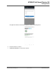
Use the following settings in the terminal emulator:
Table 4-2. Terminal Setting
Terminal Setting Value
Port Depends on platform and other devices the user has connected to
computer
ATWINC15x0 Smart Device Kit
Board Debugging
© 2019 Microchip Technology Inc.
User Guide
DS50002880A-page 40