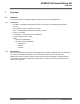
ATWINC15x0 Smart Device Kit Wi-Fi® Smart Device Enablement Kit User Guide Introduction The Wi-Fi Smart Device Enablement Kit is a small and easy demonstration and development platform for Internet of Things (IoT) solutions. It is designed to demonstrate the design of typical IoT applications. ® The kit is controlled by a SAML21G18B host MCU. It is equipped with an ATWINC15x0 IEEE 802.
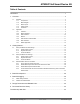
ATWINC15x0 Smart Device Kit Table of Contents Introduction .....................................................................................................................1 1. Overview....................................................................................................................4 1.1. 1.2. Hardware .....................................................................................................................................4 1.1.1. Components................................
ATWINC15x0 Smart Device Kit Customer Change Notification Service..........................................................................44 Customer Support......................................................................................................... 44 Microchip Devices Code Protection Feature................................................................. 44 Legal Notice...................................................................................................................
ATWINC15x0 Smart Device Kit Overview 1. 1.1 Overview Hardware This section describes the hardware details of the Wi-Fi Smart Device Enablement Kit. 1.1.
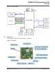
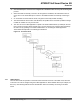
ATWINC15x0 Smart Device Kit Overview Figure 1-1. Block Diagram 1.1.3 Board Layout The following are the top and bottom side layout of the board. Figure 1-2. Top Side © 2019 Microchip Technology Inc.
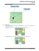
ATWINC15x0 Smart Device Kit Overview Figure 1-3. Bottom Side 1.1.4 Power Supply The board can be powered-up by USB power or a TR14500 lithium (3.7V) battery. The jumper J6 is used to select the power source. For USB power – Short the jumper (shown in red) as shown in the following image. For Lithium battery – Short the jumper (shown in blue) as shown in the following image. © 2019 Microchip Technology Inc.
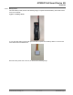
ATWINC15x0 Smart Device Kit Overview 1.1.4.1 Battery Holder The AAx1 battery holder, shown in the following image, is required to hold the battery. This holder can be found on the website. Figure 1-4. Battery Holder A 3 pin wire cable male connector with pitch 2.54 mm is required for the battery holder to connect to the Wi-Fi Smart Device Enablement Kit. Build the battery holder with connector, as shown in the following image. © 2019 Microchip Technology Inc.
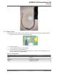
ATWINC15x0 Smart Device Kit Overview 1.1.4.2 Battery Charging A lithium battery can be charged up using USB power. Perform the following steps to charge the battery: 1. Short the Jumper J6, as shown in the following image: 2. 3. 4. Short the Jumper J4. Connect the lithium battery to connector BAT1. Plug in USB power to micro-USB port (J1). LD1 color indicates the battery charging status, when LD1 is yellow, remove the USB power. The indication is shown in the following table. Table 1-1.
ATWINC15x0 Smart Device Kit Overview CAUTION 1.1.5 Overcharging is not recommended as the package does not include the rechargeable battery and the board does not undergo the overcharging test. Schematic The schematic of the board can be downloaded from GitHub. 1.2 Application The Wi-Fi Smart Device Enablement Kit is pre-programmed and configured for demonstrating connectivity to the AWS IoT cloud, working with Amazon Alexa.
ATWINC15x0 Smart Device Kit Overview 2. 3. 4. 5. 6. 1.2.3 The board attempts to connect to the configured AP. LD2 blinks in blue for every 500 ms during this process. When the board successfully connects to AP and gets the IP address, the LED blinks in blue for every 100 ms. The board attempts to connect to the AWS Cloud after successfully connecting to AP. On successful connection with the cloud, LD2 glows continuously instead of blinking.
ATWINC15x0 Smart Device Kit Overview Table 1-2. LD2 Indication Before Connecting to the AWS Cloud LD2 color Red Status Blinks for every 0.5s The kit is in the Network Provisioning mode (AP mode). Blinks for every 100 ms Blue Green Descriptions The kit is in the Network Provisioning mode (AP mode). Mobile application successfully connects to the kit for network configuration. Blinks for every 0.5s Attempts to connect to the AP.
ATWINC15x0 Smart Device Kit Overview AWS IoT. When the board is configured to connect to an Access Point, it can connect to the AWS IoT endpoint. A Lambda function running on AWS Cloud registers the board to the AWS IoT when the board connects to the AWS IoT endpoint the first time. 1.2.6 MCU Firmware The MCU firmware source code can be download from GitHub here. Developers can follow the developer guide to customize the application. 1.2.
ATWINC15x0 Smart Device Kit Getting Started 2. Getting Started 2.1 Set Up the Board with Android App This section details how to create the account, register and control the board using the mobile application. 2.1.1 Create a User Account To use the board, the user must create a user account. Perform the following steps to create and sign up for a user account using the mobile application. 1. Launch the mobile application. Click Sign up (below the Sign in button). 2.
ATWINC15x0 Smart Device Kit Getting Started 3. A confirmation code is sent to the email. Check the email and enter the confirmation code as shown in the following screenshot. If the confirmation code is correct, a success message is shown and the user account is successfully created. The user can use this account to log in to the mobile application and enable Alexa Skill in the Alexa app when the Alexa feature is set up. 2.1.
ATWINC15x0 Smart Device Kit Getting Started 2. Log in to the application using user account. 3. The application shows the registered devices. Initially, the list is empty. 4. Tap Add devices option. Instructions to provision the network are shown in the application. © 2019 Microchip Technology Inc.
ATWINC15x0 Smart Device Kit Getting Started 5. 6. Follow the instructions, and plug in USB power to the USB port or use a lithium battery to provide power. For power supply settings, see 1.1.4 Power Supply. Connect J8 jumper (pin 2 and pin 3) to switch on the board as shown in the following image. © 2019 Microchip Technology Inc.
ATWINC15x0 Smart Device Kit Getting Started 7. 8. Hold and press the SW3 key for 5 seconds. LD2 blinks red, as the board enters to the Network Provisioning mode. LD2 blinks red for every 0.5 sec. Tap Next on the mobile application. The following screen is displayed. There are two methods to connect the board for registration. Method 1 – scans the QR code on the label of the ATWINC1510 module. 9. Method 2 – searches the board by performing Wi-Fi scan.
ATWINC15x0 Smart Device Kit Getting Started 11. Enter the password of the network, and tap OK. 12. Enter the Device Name, and tap Set. A loading screen is shown to display the provisioning is in progress. © 2019 Microchip Technology Inc.
ATWINC15x0 Smart Device Kit Getting Started 13. On successful provisioning, the application lists the device list. 2.1.3 Control the Board The user can use the mobile application to monitor or control the Wi-Fi Smart Device Enablement Kit. After the user registers the board using the mobile application, they can select the board on the application. The following screen is shown to monitor or control the board: © 2019 Microchip Technology Inc.
ATWINC15x0 Smart Device Kit Getting Started Figure 2-1. Demo Kit Screen 2.2 Set Up the Board with iOS App This section details how to create the account, register and control the board using the mobile application. 2.2.1 Create a User Account To use the board, the user must create a user account. Perform the following steps to create and sign up for a user account using the iOS mobile application. 1. Launch the mobile application. Click Sign up (below the Sign in button).
ATWINC15x0 Smart Device Kit Getting Started 2. Enter the Username, Password, and Email and click Sign up button. 3. A confirmation code is sent to the email. Check the email and enter the confirmation code as shown in the following screenshot. © 2019 Microchip Technology Inc.
ATWINC15x0 Smart Device Kit Getting Started If the confirmation code is correct, a success message is shown and the user account is successfully created. The user can use this account to log in to the mobile application and enable Alexa Skill in the Alexa app when the Alexa feature is set up. 2.2.2 Register the Board To control the board, the user must register the board to their user account.
ATWINC15x0 Smart Device Kit Getting Started 3. The application shows the registered devices. Initially, the list is empty. 4. Tap Add devices option. Instructions to provision the network are shown in the application. © 2019 Microchip Technology Inc.
ATWINC15x0 Smart Device Kit Getting Started 5. 6. 7. Follow the instructions, and plug in USB power to the USB port or use a lithium battery to provide power. For power supply settings, see 1.1.4 Power Supply. Connect J8 jumper (pin 2 and pin 3) to switch on the board as shown in the following image. 8. Hold and press SW3 key for 5 seconds. LD2 blinks red as the board enters to the Network Provisioning mode. LD2 blinks red for every 0.5 sec. Tap Network Provisioning on the mobile application.
ATWINC15x0 Smart Device Kit Getting Started 10. Select the board Wi-Fi Network (WiFiSmartDevice_F8F005XXXXXX). 11. Go back to the app and click the Next button. 12. Enter the Network SSID and password. (Only networks with WPA or WPA2 can be supported). © 2019 Microchip Technology Inc.
ATWINC15x0 Smart Device Kit Getting Started 13. Enter the Device Name, and tap Set. A loading screen is shown to display the provisioning is in progress. 14. Upon successful provisioning, the application shows the device list. © 2019 Microchip Technology Inc.
ATWINC15x0 Smart Device Kit Getting Started 2.2.3 Control the Board The user can use the mobile application to monitor or control the Wi-Fi Smart Device Enablement Kit. After the user uses the mobile application to register the board, they can select the board on the application GUI. The following screen is shown to monitor or control the board: Figure 2-2. Demo Kit Screen © 2019 Microchip Technology Inc.
ATWINC15x0 Smart Device Kit Getting Started 2.3 Enable Amazon Alexa on the Board Amazon Alexa is a voice assistant developed by Amazon. With Amazon Alexa, the board can function with a set of voice commands. Alexa Skill is a set of capabilities. Amazon allows developers to build the skills and publish skills for Alexa.
ATWINC15x0 Smart Device Kit Getting Started addition to the voice control, the user can also control the board LED LD2 either on the Alexa mobile application or on the Wi-Fi Smart Device Enablement Kit Mobile application (see 2.1.3 Control the Board). Figure 2-4. Microchip Wi-Fi Smart Device Smart Home Skill Table 2-2. Function List Function 2.3.
ATWINC15x0 Smart Device Kit Getting Started 4. Tap ENABLE TO USE. 5. Enter the Username and Password created in 2.1.1 Create a User Account/2.2.1 Create a User Account and tap Sign in. © 2019 Microchip Technology Inc.
ATWINC15x0 Smart Device Kit Getting Started The application will show that the Microchip Sensor Skill is successfully linked. 6. 7. Close this window to continue. Tap Discover Devices in to discover the devices. © 2019 Microchip Technology Inc.
ATWINC15x0 Smart Device Kit Getting Started The application shows that Alexa is discovering devices. 8. When one light device is found, the following screen appears. © 2019 Microchip Technology Inc.
ATWINC15x0 Smart Device Kit Getting Started 9. Tap SET UP DEVICE option. 10. Tap SKIP to skip adding the device to a group. Demo Kit is set up successfully. © 2019 Microchip Technology Inc.
ATWINC15x0 Smart Device Kit Getting Started 11. Select the Devices icon, and tap Lights. A Device can be found in this page (in this case, the device name is “Demo Kit”). © 2019 Microchip Technology Inc.
ATWINC15x0 Smart Device Kit Getting Started 12. Tap the device icon. User can turn on/off and control the light intensity of the LED LD2 on this page of the Alexa mobile application. 2.3.3 Enable Microchip Sensor Board Skill Perform the following steps to enable Microchip Sensor Board Skill. 1. 2. Launch Alexa mobile application, and tap ”≡” in the upper left hand corner. Select Skills. © 2019 Microchip Technology Inc.
ATWINC15x0 Smart Device Kit Getting Started 3. Type “sensor” in the search bar, then tap Microchip Sensor Skill. 4. Tap ENABLE. © 2019 Microchip Technology Inc.
ATWINC15x0 Smart Device Kit Getting Started 5. Enter the Username and Password created in 2.1.1 Create a User Account/2.2.1 Create a User Account and tap Sign in. The application will show that the Microchip Sensor Board Skill is successfully linked. 2.3.4 Control and Monitor the Wi-Fi Smart Device Enablement Kit Using Voice Commands with Echo Dot 2.3.4.1 Voice Control of Microchip Wi-Fi Smart Device Smart Home Skill For the detailed function list of the voice command, see 2.
ATWINC15x0 Smart Device Kit Getting Started Usage – Turn on/off the LED LD2 User – Alexa, turn on demo kit. Echo Dot – Ok Usage – Set the light intensity of LED LD2 User – Alexa, set the power to 60% on demo kit. Echo Dot – Ok 2.3.4.2 Voice Control of Microchip Sensor Board Skill For the detailed function list of the voice command, see 2.3 Enable Amazon Alexa on the Board. Note: User needs to say “Alexa” to prefix opening the sensor board.
ATWINC15x0 Smart Device Kit Board Development 3. Board Development Developers can customize the board features by modifying the firmware. The board is pre-programmed with a bootloader. A developer can use Atmel Studio to compile the firmware and program the firmware to the board with SAM-BA in-system programmer through USB interface. If developers need to use a debugger for development, Atmel-ICE is required. Firmware is programmed to the board through SWD interface by Atmel-ICE.
ATWINC15x0 Smart Device Kit Board Debugging 4. Board Debugging 4.1 UART Debug Interface The Wi-Fi Smart Device Enablement Kit has debug UART pins. The pins are connected to the J9 connector. The user can utilize a USB-to-UART converter to connect the computer, and the board Debug UART to capture the MCU log. Figure 4-1. UART Debug Interface Table 4-1. UART Debug Interface Pin Details Pin 4.
ATWINC15x0 Smart Device Kit Board Debugging ...........continued Terminal Setting Value BAUD rate 115200 Data 8 bit Parity none Stop 1 bit Flow control none Figure 4-2. Application Boot Up Log © 2019 Microchip Technology Inc.
ATWINC15x0 Smart Device Kit Design Documents and Related Links 5. Design Documents and Related Links • • • • • • ATWINC15x0 Module Datasheet SAML21G18B Host MCU ATECC608A CryptoAuthentication™ Device BME280 Demo application firmware and mobile application software Wi-Fi Sensor board schematics © 2019 Microchip Technology Inc.
ATWINC15x0 Smart Device Kit Document Revision History 6. Document Revision History Revision Date Section Description A 05/2019 Document Initial Revision Regulatory Notice: The unit is a development/evaluation tool which is designed to be used for research and development in a laboratory environment. The unit is not intended to be a finished appliance, nor is it intended for incorporation into finished appliances that are made commercially available as single functional units to end users.
ATWINC15x0 Smart Device Kit The Microchip Web Site Microchip provides online support via our web site at http://www.microchip.com/. This web site is used as a means to make files and information easily available to customers.
ATWINC15x0 Smart Device Kit • Neither Microchip nor any other semiconductor manufacturer can guarantee the security of their code. Code protection does not mean that we are guaranteeing the product as “unbreakable.” Code protection is constantly evolving. We at Microchip are committed to continuously improving the code protection features of our products. Attempts to break Microchip’s code protection feature may be a violation of the Digital Millennium Copyright Act.
ATWINC15x0 Smart Device Kit © 2019, Microchip Technology Incorporated, Printed in the U.S.A., All Rights Reserved. ISBN: 978-1-5224-4473-2 Quality Management System Certified by DNV ISO/TS 16949 Microchip received ISO/TS-16949:2009 certification for its worldwide headquarters, design and wafer fabrication facilities in Chandler and Tempe, Arizona; Gresham, Oregon and design centers in California and India.
Worldwide Sales and Service AMERICAS ASIA/PACIFIC ASIA/PACIFIC EUROPE Corporate Office 2355 West Chandler Blvd. Chandler, AZ 85224-6199 Tel: 480-792-7200 Fax: 480-792-7277 Technical Support: http://www.microchip.com/ support Web Address: www.microchip.