
User`s guide


External Memory Handling
© 2006 Microchip Technology Inc. DS51519B-page 77
5.2.5 External Memory Interface
The External Memory Interface is a feature that allows the microcontroller to access
external memory devices (such as Flash, EPROM, SRAM, etc.) as program or data
memory.
PIC17 Devices
When either Microprocessor or Extended Microcontroller mode is selected, PORTC,
PORTD and PORTE are configured as the system bus. PORTC and PORTD are the
multiplexed address/data bus and PORTE<2:0> is for the control signals. External
components are needed to demultiplex the address and data.
For more information, see the Memory Organization, External Memory Interface
section of the device data sheet.
PIC18 Devices
Using the MEMCON register, the following may be configured:
• External bus enable and disable
• 16-Bit mode – Word Write mode, Byte Select mode or Byte Write mode
• Wait – Table read/write bus cycle wait counts (0-3 T
CY)
For more information, see the External Memory Interface section of the device data
sheet.
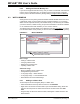
5.3 EXTERNAL MEMORY ENABLED IN MPLAB IDE
To set up MPLAB IDE (and a selected debug tool) to recognize external memory, select
Configure>External Memory
. Then check “Use External Memory” and enter a range.
See Section 13.9 “External Memory Setting Dialog” for more on this dialog.
Some debug tools may require additional setup for external memory, usually on the
Debugger>Settings
dialog. See the documentation for the tool for more information.
5.4 PROGRAM MEMORY WINDOW
The Program Memory window will contain all enabled program memory, i.e., on-chip,
external or a combination of both. See Section 12.8 “Program Memory Window” for
more on this window.
For hardware tools, external memory contents may need to be uploaded before the
current values are reflected in this window.