
User`s guide


MPLAB
®
IDE User’s Guide
DS51519B-page 244 © 2006 Microchip Technology Inc.
•Action
Type = Asynch:
Pulse: Change the state of the pin to its opposite and return.
High: Change the state of the pin to high.
Low: Change the state of the pin to low.
Toggle: Change to state of the pin to its opposite.
Type = Synch: Clock
• High cycles – number of cycles high state will be applied for Synch stimulus.
• Low cycles – number of cycles low state will be applied for Synch stimulus.
• Invert – inverts high and low cycles when checked for Synch stimulus.
• Comments – allows you to specify a comment which will be saved and restored if
you maintain Pin Stimulus in a file.
19.3 USING FILE STIMULUS
MPLAB SIM triggers changes to pin and register values specified in a file by using File
Stimulus. These files specify values that will be sent to a pin or register when a trigger
is fired. This trigger may be a cycle count for pins or a program memory address for
registers.
• Creating/Editing File Stimulus
• Applying File Stimulus
• File Stimulus Display
19.3.1 Creating/Editing File Stimulus
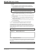
Select Debugger>Stimulus Controller and then click the File Stimulus tab. A File
Stimulus file is composed of one or more Synchronous Stimulus files. A Synchronous
Stimulus file contains information on triggers used for applying stimulus to either a pin
or register. Register stimulus is specified in a Register Stimulus file.
• Creating/Editing a File Stimulus File (.fsti)
• Creating/Editing a Synchronous Stimulus File (.ssti)
• Creating/Editing a Register Stimulus File (.rsti)
Note 1: Changing stimulus files outside the Stimulus dialog is NOT
recommended.
2: If you have already set pin stimulus on a port pin, you will not be able to
inject stimulus into that pin or corresponding register using file stimulus.
MyStimulus.fsti
SyncStimulus1.ssti
SyncStimulus2.ssti
SyncStimulus3.ssti
TRISBStimulus.rsti
TRISBStimulus.rsti
T1CONStimulus.rsti