
User`s guide


Using Stimulus
© 2006 Microchip Technology Inc. DS51519B-page 235
To Change the Order of Signals on the Pin/Register tab:
• Click on the signal from the “Selected Signals” list.
• Click either Move Up or Move Down to change order of this signal in the list.
•Click OK.
Its location will now be reflected in the order of the column heads on the associated
Pin/Register tab.
18.2.4 Clock Stimulus
Pulse (high and low) values applied to a pin is clocked stimulus as shown in Table 18-3.
Clocked stimulus may be entered here.
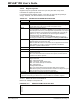
TABLE 18-3: DEFINITIONS OF CLOCK STIMULUS
Item Definition
Label Name the clock stimulus you are specifying (optional).
Pin Choose the pin on which you will apply clocked stimulus.
Initial Enter the initial state of the clocked stimulus, either low or high.
Low Cycles Enter a value for the number of low cycles in a clock pulse.
High Cycles Enter a value for the number of high cycles in a clock pulse.
Begin Click here to activate the selection in the Begin section:
Always (default) Begin stimulus immediately on program run.
PC= Begin stimulus when the program counter equals the
entered value.
Cycle= Begin stimulus when the instruction cycle count equals
the entered value. This is always expressed in absolute
time, i.e., from the beginning of simulation. The End
Cycle may be expressed relative to the beginning of
simulation or this Begin Cycle (see below).
Pin= Begin stimulus when the selected pin has the selected
value (low or high).
End Click here to activate the selection in the End section:
Never (default) Apply stimulus until program halt.
PC= End stimulus when the program counter equals the
entered value.
Cycle= End stimulus when the instruction cycle count equals the
entered value.
absolute time (cyc) – relative to the beginning of
simulation.
from clock start (cyc+) – relative to the Begin Cycle (see
above).
Pin= End stimulus when the selected pin has the selected
value (low or high).
Comments Add descriptive information about the stimulus.