
User`s guide


MPLAB
®
IDE User’s Guide
DS51519B-page 234 © 2006 Microchip Technology Inc.
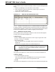
For the condition set up in the previous example, COND1, set up the following stimulus
trigger:
1. Make the pin RB0 high for the first instance of the condition.
2. Wait 10 instruction cycles and check for the condition again. If and when it
occurs, make pin RB0 high again.
3. Repeat step 2 until the program is halted.
EXAMPLE 18-2: MAKE PIN HIGH ON REGISTER VALUE
18.2.2.3 “DEFINE CONDITIONS” WAIT VS. “DEFINE TRIGGER” RE-ARM DELAY
In “Define Conditions”, the Wait time refers to the time from when the condition is true
until the stimulus is applied. In “Define Trigger”, the post-trigger delay is time from when
the stimulus was applied until the condition for triggering is checked again.
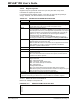
18.2.3 Add/Remove Signals Dialog
Use this dialog to add or remove pins or registers to which stimulus will be applied
according to the associated Pin/Register tab.
To Add a Signal:
• From the “Available Signals” drop-down box, select a type of signal, either “SFR
and Field”, “Pin Only” or “All Signals”.
• In the list below, either:
- Click on a signal and then click Add to add the signal to the “Selected
Signals” list.
- Double click on a signal to add it to the “Selected Signals” list.
•Click OK.
This signal will now appear as a column head on the associated Pin/Register tab.
To Delete a Signal:
• In the “Selected Signals” list, either:
- Click on the signal and then click Remove to remove the signal from this list.
- Double click on the signal to remove the signal from this list.
•Click OK.
This signal will now not appear as a column head on the associated Pin/Register tab.
Note: Pins that support peripheral I/O (e.g., CCP2) as well as digital I/O
(e.g., RB3 or RC1) will only be listed by the digital I/O name, although the
peripheral I/O function will be available if properly configured and
supported in the simulator.