
User`s guide


Using Stimulus
© 2006 Microchip Technology Inc. DS51519B-page 233
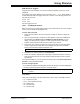
As an example, set up a condition, COND1, such that when the value of register
PORTC equals FF, stimulus defined in “Define Triggers” is applied 10 ms later.
EXAMPLE 18-1: REGISTER EQUALS A VALUE
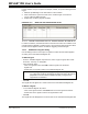
18.2.2.2 DEFINE TRIGGERS
Define stimulus triggers in each row of this section as shown in Table 18-2, with
reference to the conditions set up in “Define Conditions”.
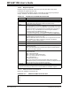
To scroll through signals:
• If you add more signals than will fit in the window, a scroll bar will appear.
• You may scroll through all the signals to view their values.
Note: If PORTC has an initial value of FF, or never changes to FF, the condition
will never be met and no stimulus will be applied.
TABLE 18-2: DEFINITIONS OF STIMULUS TRIGGERS
Item Definition
Enable Alternately enable or disable the trigger setup in this row.
Condition Refers to the label of the condition set up in the “Define Conditions” section
of this tab. Select a condition from the list.
Type Select whether the trigger condition will apply once (1x) or continuously/
repeatedly (Cont).
Re-Arm Delay If Type = Cont, then enter a delay until the trigger condition is checked
again. The delay value is entered in the first column and the delay value unit
is selected in the second column.
Click Here to
Add Signals
Click on the text that says “(Click here to add/remove signals)” to open the
Add/Remove Signals dialog (see Section 18.2.3 “Add/Remove Signals
Dialog”). In this dialog, you select the pins, registers or other signals to
which you will apply stimulus. These selections will become the titles of the
columns.
Note: The columns to the left of the signal column(s) remains fixed when you
scroll through the signal columns.