
User`s guide


MPLAB
®
IDE User’s Guide
DS51519B-page 232 © 2006 Microchip Technology Inc.
When h:m:s is chosen, values input in the Time column will have the following mean-
ings:
• 1 – means 1 second
• 1:00 – means 1 minute
• 60 – becomes 1:00
• 999 – becomes 16:39
• 9999999 – becomes 2777:46:39
• 1:5 – becomes 1:05
• 60:5 – becomes 1:00:05
The time value range is 0 to (2^31 – 1) seconds. Anything outside this range will be
changed to the default (0 for the first tab and re-arm delay; 1 for the condition wait).
Care should be taken when changing the time units for Time values already entered.
As an example, if a time of 100 cyc is initially specified but then the Time Units are
changed to h:m:s, 100 will be interpreted as an integer and converted into 1:40.
18.2.2 Advanced Pin/Register
Advanced (complex) synchronous pin/register actions may be entered here. For basic
actions, use the Pin/Register Actions tab.
Define your conditions first, and then define the triggers.
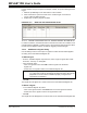
18.2.2.1 DEFINE CONDITIONS
Define the conditions for one or more stimuli in each row of this section as shown in
Table 18-1.
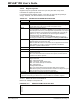
TABLE 18-1: DEFINITIONS OF STIMULI CONDITIONS
Item Definition
Condition A name for the condition you are specifying is automatically generated
when you enter data in any other column. This label will be used to identify
the condition in the Condition column of the Define Triggers section of this
tab.
When Changed Define the change condition. I.e., the condition is true when the value of the
pin/register in Column 2 (its type specified in Column 1) changes to the rela-
tionship of Column 3 to the value of Column 4.
Note: Conditions are only checked on changes, not every cycle.
Column 1: Select the type of pin/register, either “SFR”, “Bitfield”, “Pin” or
“All” of the above. This will filter the content of Column 2.
Column 2: Select the pin/register to which the condition will apply.
Column 3: Select the condition, either equal (=), not equal (!=), less than or
equal (<=), greater than or equal (>=), less than (<) or greater than (>).
Column 4: Enter the value for the condition.
Note: Care must be taken when using SFR values as triggers.
Wait Once the condition defined above is true, specify how long to wait until the
stimulus is applied.
Column 1: Wait time value.
Column 2: Wait time value units.
Comments Add descriptive information about the condition.