
User`s guide


© 2006 Microchip Technology Inc. DS51519B-page 229
MPLAB
®
IDE
USER’S GUIDE
Chapter 18. Using Stimulus
18.1 INTRODUCTION
During simulation, the program being executed by the simulator may require stimuli
from the outside. This stimulus could be a level change or a pulse to an I/O pin of a port.
It could be a change to the values in an SFR (Special Function Register) or other data
memory.
In addition, stimulus may need to happen at a certain instruction cycle or time during
the simulation. Alternately, stimulus may need to occur when a condition is satisfied;
for example, when the execution of program has reached a certain instruction address
during simulation.
Basically, there are two types of stimulus:
• Synchronous – A predefined series of signal changes to an I/O pin, SFR or GPR
(e.g., a clock cycle).
• Asynchronous – A one-time change to the I/O pin or RCREG triggered by the a fir-
ing button on the IDE.
To define when, what and how external stimuli are to happen to a program, you would
use the following:
• SCL Generator Dialog - Use the tabs on this dialog to create an SCL stimulus file
(i.e., a workbook) for synchronous stimulus.
• Stimulus Controller Dialog - Control stimulus with this dialog. Attach an SCL stim-
ulus file (from the SCL Generator dialog), and/or enter asynchronous stimulus on
this dialog.
If you will be using multiple forms of stimulus input, you should be aware of input inter-
action (see Section 18.4 “Stimulus Input Interaction”).
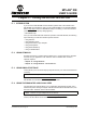
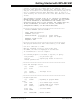
FIGURE 18-1: SIMULATOR STIMULUS
SCL Generator Dialog
Stimulus Controller Dialog
Workbook
Scenario
MPLAB
®
SIM Simulator
Stimulus
Synchronous
Asynchronous
Stimulus
Stimulus
File
File
SCL
File