
User`s guide


Getting Started with MPLAB SIM
© 2006 Microchip Technology Inc. DS51519B-page 225
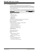
17.7.1 PIC18F MCU USART Example – Setup
Follow the steps below to set up the example.
1. Example code for demonstrating USART operation in the simulator is based on
code found on the Microchip website under “PICDEM
™
2 example code” as
“USART demo for the 18CXXX” (usart.asm). The updated code
(usart2.asm) is listed in Section 17.7.4 “Updated PICDEM 2 Example
Code”.
2. In MPLAB IDE, use the Project Wizard to create a project.
- Select PIC18F452 as the device.
- Select “Microchip MPASM Toolsuite” as the active toolsuite. Make sure the
paths to the executables are correct.
- Place the project in its own folder and name the project “usart”.
- Add the file usart2.asm to the project. You will not use the linker in this
example, so no linker script file is needed.
3. Disable the Watchdog Timer so it will not interrupt program execution.
-Select Config
ure>Configuration Bits.
- Under the “Settings” column, select Watchdog Timer as “Disabled”.
4. Build the project (Project>Build All
). Build results are displayed on the Build tab
of the Output window. Fix any reported errors.
17.7.2 PIC18F MCU USART Example – UART IO Tab
For MPLAB IDE v7.20 and above, follow the steps below to use the UART IO tab of the
Settings dialog to simulate USART/UART operation.
1. Once the project is completed, you will need an input file to simulate USART
signal input.
-Select File>Open
to open an editor window.
- Enter message-based data for RCREG input (see
Section 18.2.5.2 “Message-Based Data File Description” for information
on this format). Example input might be:
//single-packet example
wait 20 ms
10 20 34
-Select File>Save
and name the file input.txt.
2. Now select the UART IO tab to enable and set up the USART peripheral.
-Select Debugger>Settings
, UART IO tab.
- Check “Enable UART1 I/O”.
-Select input.txt as the “Input” file. Check “Rewind Input” so the program
will read the input file again once it has reached the end-of-file.
- Click “Window” under “Output” to display USART output on the SIM UART1
tab of the Output window.
3. Build the project again and run it to see the output.
-Select Project>Build All
.
- Run the program to see the output on the SIM UART1 tab of the Output
window.