
User`s guide


MPLAB
®
IDE User’s Guide
DS51519B-page 224 © 2006 Microchip Technology Inc.
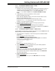
17.5 USING THE STOPWATCH
The stopwatch is useful for simple timing between program halts. Reach this dialog
from Debugger>Stopwatch
.
Instruction Cycles and Time
The simulator updates the “Instruction Cycles” and “Time” fields, including the Time
units, as your program runs.
PICmicro MCUs and dsPIC30F/PIC24F devices use 4 clock cycles per instruction to
calculate time. dsPIC33F/PIC24H devices use 2 clock cycles per instruction to
calculate time.
•Click Synch to synchronize the stopwatch to the total simulated values.
•Click Zero to set the “Instruction Cycles” and “Time” values to zero at any time.
Also, stopwatch time may be reset to zero by issuing a Processor Reset
(Debugger>Reset>Processor Reset
).
Processor Frequency
This field, including Frequency units, will be set from the Osc/Trace (or Clock for
PIC17 MCUs) tab of the Debugger>Settings
dialog.
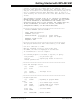
17.6 USING EXTERNAL MEMORY
Simulating a device that uses external memory requires the following steps:
1. Setting Configuration bits to enable external memory modes –
C
onfigure>Configuration Bits
2. Setting external memory usage in MPLAB IDE – Configure>External Memory
For more information on external memory and MPLAB IDE, see MPLAB IDE documen-
tation on external memory setup and use.
For the simulator, external memory is simulated the same as on-chip memory – with
PC memory. Therefore, there are no communication delays as there may be with
hardware.
17.7 USING A USART/UART
For devices that have a USART or UART peripheral, there are two ways in which to
simulate this operation:
1. Using the UART1 I/O Tab – USART/UART simulation may be enabled and set
up using the UART1 IO tab of the Settings dialog (Debugger>Settings
). For more
on this tab, see Section 21.3.4 “UART1 IO tab”.
2. Using SCL Stimulus – USART/UART simulation may accomplished using SCL
stimulus to USART registers. For more on SCL stimulus, see Chapter
18. “Using Stimulus”.
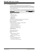
For an example of simulating USART/UART operation, see below.
• PIC18F MCU USART Example – Setup
• PIC18F MCU USART Example – UART IO Tab
• PIC18F MCU USART Example – SCL Stimulus
• Updated PICDEM 2 Example Code