
User`s guide


ZigBee™ Protocol Tools
© 2008 Microchip Technology Inc. DS51606C-page 27
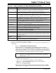
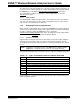
TABLE 3-12: ZigBee™ PROTOCOL PIC
®
MCU CONFIGURATION SELECTION
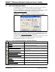
3.2.9 Generating the Configuration Files
When all the options on all the tabs are set appropriately, generate the Stack
configuration files by clicking Generate Files. The ZENA Wireless Network Analyzer
will first perform a validity check to ensure that all required fields have appropriate
values and all profile-specific ranges are met. If no endpoints are specified, the ZENA
analyzer will generate a warning, but will still generate the output files.
If the validity check passes, ZENA analyzer will prompt for an output directory for the
configuration files. These files are:
• zigbee.def – Provides basic definitions for Stack configuration.
• myZigBee.c – Provides all ROM initialization for the Stack, including
ZigBee protocol device descriptors.
• zLink.lkr – Project linker script.
Each of these files has a time and date stamp included in the file. Refer to AN965,
“Microchip Stack for the ZigBee™
Protocol” for more information about these files.
Configuration Option Description
Target Device Select the PIC
®
MCU device used by the target application. If the exact device is not
available, select a similar device and refer to AN965, “Microchip Stack for the ZigBee™
Protocol” for information on modifying the linker script for the target device.
Clock Frequency (Hz)
(1)
Specify the input clock frequency to the PIC MCU in Hertz. It is important that this value be
accurate as all internal ZigBee™ protocol timing will be based off of this value.
UART Baud Rate If you are using the UART of the target device and you are using the interface code pro-
vided in AN965, “Microchip Stack for the ZigBee™ Protocol”, specify the UART baud rate.
If your application does not use the UART, this value is irrelevant.
Heap Size (banks) Specify the number of banks of heap space required by the application. Refer to AN965,
“Microchip Stack for the ZigBee™ Protocol” for information on setting the heap size.
Stack Size (banks) Specify the number of banks required for the C software Stack. Refer to AN965, “Microchip
Stack for the ZigBee™ Protocol” for information on setting the Stack size.
Build Target Select whether you want the linker script generated for a debug environment using
MPLAB
®
ICD 2 or for a production build.
Program Memory Select this radio button if all nonvolatile tables will be stored in program memory. This
option may not be available depending on the Target Device family and erase block size.
SPI Serial EEPROM Select this radio button if all nonvolatile tables will be stored in an SPI serial EEPROM. This
option may not be available depending on transceiver settings.
Serial EEPROM Select the serial EEPROM that will be used. If your EEPROM is not listed, select Other and
specify the Number of Bytes and Page Size.
nCS Select the serial EEPROM’s chip select pin.
(2)
SPI Select which SPI module to use for the serial EEPROM. The availability of this option
depends on transceiver selection and whether shared SPI has been enabled. See Allow
Shared SPI in Table 3-2.
MAC Address Stored
Externally
Select this option if the device’s MAC address will be preprogrammed into the serial
EEPROM.
Verify Writes Select this option to write to the nonvolatile storage until the data reads back identically.
This ensures accuracy, but could result in an infinite loop.
Note 1: The PICDEM™ Z Demonstration Board has a clock frequency of 16 MHz (16000000 Hz) if the PLL is enabled.
If the PLL is not enabled, the clock frequency is 4 MHz.
2: Ensure the pin exists on the target device. The application code is responsible for configuring the pin as a
digital output.
Note: Many options, including endpoint specification, affect multiple output files.
Therefore, it is recommended not to mix and match files from different
ZENA analyzer sessions.