
User`s guide

ZENA™ Wireless Network Analyzer User’s Guide
DS51606C-page 14 © 2008 Microchip Technology Inc.
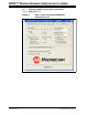
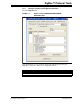
3.2.2 Specifying Transceiver Information
Select the Transceiver tab.
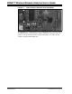
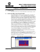
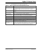
FIGURE 3-2: ZENA™ STACK CONFIGURATION WINDOW,
TRANSCEIVER TAB
Using this window, you can configure the following items:
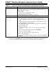
TABLE 3-2: ZigBee™ PROTOCOL TRANSCEIVER CONFIGURATION SELECTION
Configuration Option Description
Transceiver Selects one of the transceivers supported by the Stack.
Frequency
Band
This combo box shows the various available frequency bands of the selected transceiver. If the transceiver
supports only one frequency band, that frequency will be displayed and the combo box will be disabled.
Output Power Selects the initial output power of the transceiver.
Pin
Assignments
(1)
This panel shows the required pins for the selected transceiver. The Stack allows you to change these pin
connections to application-specific port pins.
PICDEM™ Z
Pins
Click this button to restore the pin assignments to the connections used by the PICDEM Z Demonstration
Board.
Allowed
Channels
This area shows the channels that are supported by the selected frequency band. Selecting channels
here will generate a label that can be used to specify the allowed channels for network formation and
network discovery. Click Clear All to uncheck all channels and click Select All to check all channels.
Each channel can also be checked or unchecked individually by clicking on the checkbox that precedes
the channel number.
Allow Shared
SPI
Some transceivers require a dedicated SPI unless additional hardware is provided. If you are using an
SPI serial EEPROM for external nonvolatile storage, and you want the transceiver and EEPROM to use
the same SPI peripheral, select this option to allow additional option selection on the PIC
®
MCU page.
Note 1: Ensure the pin exists on the target device. The application code is responsible for configuring the pin as a
digital input or output as appropriate.