
User`s guide

PICDEM Z Demonstration Kit User’s Guide
DS51524C-page 26 © 2008 Microchip Technology Inc.
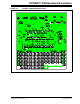
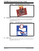
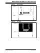
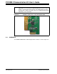
FIGURE C-1: PICDEM™ Z MRF24J40 2.4 GHZ DAUGHTER CARD
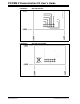
C.3 SCHEMATIC
The PICDEM Z MRF24J40 2.4 GHz Daughter Card schematic is shown in Figure C-2.
Note: The MRF24J40 SDO pin 17 defaults to a low state when nCS is high (the
MRF24J40 is not selected). If the MRF24J40 Daughter Card is to share an
SPI bus, a tri-state buffer can be placed on the SDO signal to provide a
high-impedance signal to the SPI bus. Refer to the “MRF24J40 Data Sheet”
(DS39776) for more information.