
User`s guide

PICDEM Z Demonstration Kit User’s Guide
DS51524C-page 20 © 2008 Microchip Technology Inc.
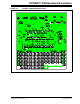
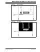
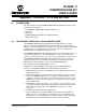
FIGURE B-1: MRF24J40MA PICDEM™ Z 2.4 GHz RF BOARD
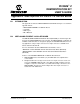
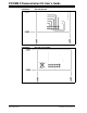
B.3 SCHEMATIC
The schematic for the MRF24J40MA module is available in the MRF24J40MA Data
Sheet (DS70329). Figure B-2 shows the schematic of the daughter board with the
MRF24J40MA module mounted on it.
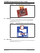
FIGURE B-2: MRF24J40MA PICDEM™ Z GHZ RF BOARD SCHEMATIC
B.4 PCB LAYOUT
Figure B-3 through Figure B-6 show the PCB layout of the daughter board without the
MRF24J40MA module mounted on it.
C1
0.1æF
P1
1
2
3
4
5
6
7
8
9
10
11
12
MRF24J40MA
U1
GND
RESET
WAKE
INT
SDI
SCK SDO
CS
CLKOUT
GND
Vin
GND
1
2
3
4
5
67
8
9
10
11
12
NC
NC
NC
NC