
User`s guide

© 2008 Microchip Technology Inc. DS51524C-page 19
PICDEM
™
Z
DEMONSTRATION KIT
USER’S GUIDE
Appendix B. MRF24J40MA PICDEM Z 2.4 GHz RF Board
B.1 INTRODUCTION
This appendix describes the MRF24J40MA Z 2.4 GHz RF Board. Topics covered in this
appendix include:
• MRF24J40MA PICDEM Z 2.4 GHz RF Board
•Schematic
•PCB Layout
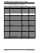
• Bill of Materials
B.2 MRF24J40MA PICDEM Z 2.4 GHz RF BOARD
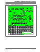
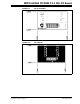
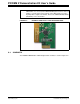
The MRF24J40MA PICDEM Z 2.4GHz RF Board (AC163028) is shown in Figure B-1.
It features the MRF24J40MA transceiver module. The MRF24J40MA is a fully FCC, IC
and ETSI certified module. It is designed to plug into the PICDEM Z Motherboard, or to
any application, using a 12-pin connector. The 12-pin connector is available from
Samtec P/N LST-106-07-F-D.
For more information about the MRF24J40 IC and module, refer to:
“MRF24J40 2.4 GHz IEEE 802.15.4 RF Transceiver Data Sheet” (DS39776)
“MRF24J40MA 2.4 GHz IEEE 802.15.4 RF Transceiver Module Data Sheet”
(DS70329)
Features of the PICDEM Z MRF24J40 2.4 GHz RF Board include:
1. MRF24J40MA Transceiver Module (U1): An IEEE 802.15.4 compliant trans-
ceiver module.
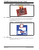
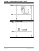
2. Daughter Card Connector (P1): Connector P1 is a 12-pin connector used to con-
nect to the PICDEM Z Motherboard or any application with a mating connector.
It supplies 3.3V power, 4-wire SPI, reset, wake and interrupt connections to the
MRF24J40MA. The pinout is shown in Figure B-2. The 12-pin connector is a
Samtec P/N LST-106-07-F-D.