
User`s guide

Overview
© 2008 Microchip Technology Inc. DS51524C-page 9
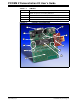
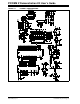
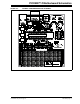
FIGURE 1-3: CONNECTOR J2 PINOUT
1.5 WIRELESS DAUGHTER BOARDS
The PICDEM Z Motherboard is designed to interface with a variety of wireless daughter
boards via connector J2. Connector J2 is a 12-pin connector that supplies 3.3V power,
4-wire SPI, reset, wake and interrupt connections to the microcontroller. The pinout is
shown in Figure 1-3. The 12-pin connector is a Samtec P/N LST-106-07-F-D.
1.6 PICDEM™ Z CD-ROM
The PICDEM Z CD-ROM contains documentation on the motherboard, wireless
daughter boards, data sheets, application notes and wireless protocol software. Check
the Microchip web site for the latest revisions http://www.microchip.com/wireless/.
+3.3V
INT
MOSI
SCK
MISO
WAKE
GND 12
34
56
78
910
1112
J2
RB0
RC5
RC3
RB2
RC2
SignalPin Microcontroller
RB3
RB1
RC4
RC0
RC1
Signal PinMicrocontroller
(Top view on Motherboard)
RESET
CS