
User`s guide

Overview
© 2008 Microchip Technology Inc. DS51524C-page 7
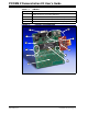
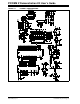
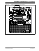
1.4 PICDEM™ Z MOTHERBOARD
The PICDEM Z Motherboard contains many features to enable the evaluation and
development of wireless solutions. Figure 1-2 shows the motherboard with a
MRF24J40MA Module Daughter Board plugged in. Below is a description of the call
outs in the figure. The motherboard schematic, PCB layout and bill of materials are
available in Appendix A.
1. Microcontroller 28 and 40-pin DIP Sockets: The sockets allow the use of a variety
of 28 and 40-pin DIP package PIC
®
microcontrollers. The 40-pin socket (U4)
contains a PIC18LF4620 microcontroller clocked by a 4 MHz crystal (Y1). The
28-pin socket is unpopulated and is located under the 40-pin DIP package. To
use the 28-pin connector, carefully remove the 40-pin DIP microcontroller.
2. Temperature Sensor: The motherboard contains the Microchip TC77 thermal
sensor with SPI interface. The TC77 shares the SPI bus with the wireless
daughter card plugged into connector J2.
3. LEDs: D1 and D2 are driven by microcontroller ports RA0 and RA1, respectively.
4. Push Button Switches: S2 and S3 are connected to microcontroller ports RB5
and RB4, respectively. There are no external pull-up resistors on the mother-
board. Therefore, the internal pull-up on PORTB feature must be enabled.
5. MCLR
Push Button Switch: Connected to the MCLR pin of the microcontroller.
6. ICSP™ Jack: The 6-pin RJ-11 jack is used to connect a microcontroller program-
mer such as the MPLAB ICD 2 in-circuit debugger or MPLAB REAL ICE™
in-circuit emulator.
7. RS-232 Connector: Allows the motherboard to connect to a PC serial port for
interactive control or debugging. The microcontroller USART interfaces to the
RS-232 connector via a RS-232 level shifter (U5).
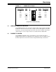
8. Wireless Daughter Card Connector: Connector J2 is a 12-pin connector that sup-
plies 3.3V power, 4-wire SPI, reset, wake and interrupt connections to the micro-
controller. The pinout is shown in Figure 1-3. The 12-pin connector is a Samtec
P/N LST-106-07-F-D.
9. Prototyping Area: Provided to breadboard additional circuitry for development.
Connections to +3.3V, ground and microcontroller I/O signals are provided.
10. Power: The motherboard is powered by an external power supply via the 2.5 mm
coaxial power connector (J1) or portably via a 9V battery (B1). The on-board volt-
age regulator (U2) is a LP2981, a micropower 100 mA ultra low-dropout regulator
in a SOT-23 package. The maximum input voltage for the LP2981 is 16V. The
motherboard is protected from accidental reverse power connection by diode D3.
When using a 9V battery, S7 switches the power on and off. When powering via
an external power supply, J1 will disconnect the battery from the circuit and
power the circuit continuously (switch S7 only switches the battery on or off, not
the external power source).
11. Measure Current: Jumper JP4 can be used to measure the current draw by all
the circuitry on the motherboard past the voltage regulator (U2). To measure the
current, cut the PCB trace on the bottom side and insert an ampmeter. You can
also install a low value resistor into position R9 and measure the voltage across
to determine the current.
CAUTION
Do not exceed the combined current rating of 100 mA for all circuitry or the voltage
regulator will overheat and possibly fail.
Note: A 9V wall adapter may be ordered from microchipDIRECT under part
number AC162039.