
User manual

Installation and Operation
© 2007 Microchip Technology Inc. DS51607B-page 11
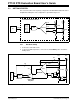
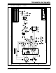
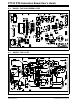
2.4.1.2 RTD SIGNAL CHAIN
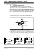
The PGA is used to amplify the small voltage across the RTD. The reference input pin
of the PGA is connected to the RTD negative terminal and Channel 0 and Channel 1
are connected to the positive terminals of each RTD. This allows only the voltage
across the sensor to be amplified. The PGA has a gain error of ±1% (max.) for gains
greater than 1 V/V. Refer to the datasheet (DS21685) for details.
The RTD negative terminal and the PGA output are connected to the differential
amplifier. The differential amplifier scales the PGA output. The difference amplifier gain
is shown in Equation 2-1.
EQUATION 2-1: DIFFERENCE AMPLIFIER GAIN
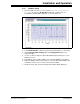
2.4.1.3 THE GRAPHICAL USER INTERFACE
The GUI uses the USB port to communicate with the PIC18F2550.
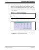
FIGURE 2-6: Hardware Status
When start is clicked, the macro double checks hardware availability before starting
the acquisition.
All user options such as Sampling time, Stripchart buffer size, Digi. Pot Positions,
or PGA Chn/Gain setup can be changed during acquisition.
G1
2R
F
×
R
G
20
Ω
+
-------------------------
⎝⎠
⎛⎞
+=
Where:
R
F
= 10 kΩ
R
G
= 10 kΩ Digital Potentiometer