
User manual

PT100 RTD Evaluation Board User’s Guide
DS51607B-page 10 © 2007 Microchip Technology Inc.
2.4 FUNCTIONAL DESCRIPTION
2.4.1 The PT100 RTD Evaluation Board
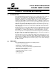
The PT100 RTD Evaluation Board uses surface mount RTD to measure
temperature. An external 2, 3, or 4-wire PT100 RTD can also be connected to measure
temperature in remote locations. The RTDs are biased using a constant current source.
In order to reduce self-heat due to power dissipation, the current magnitude is relatively
low. The small voltage across the RTD is amplified using the MCP6S26 PGA. The PGA
allows the user to digitally program the amplifier gain and increase the sensor output
range. The output of the PGA is scaled using a differential amplifier. The differential
amplifier drives a 12-Bit + sign differential ADC, MCP3301. The digital data is read
using PIC18F2550 and transmitted to PC using a USB interface.
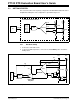
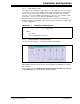
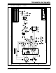
2.4.1.1 THE RTD BIASING CONSTANT CURRENT SOURCE
The constant current source uses a reference voltage, one amplifier, and a PNP
transistor, as shown in Figure 2-4.
FIGURE 2-4: Constant Current Source.
The amplifier maintains constant voltage at the transistor emitter terminal. Therefore,
the emitter and collector currents are constant. The collector current biases the RTD.
The biasing current can be fine tuned by adjusting the 10 kΩ digital potentiometer using
the GUI. A 100Ω, 0.1% resistor is available for system calibration at 0°C (RTD
resistance at 0°C is 100Ω). This resistor can be jumped using JP1.
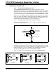
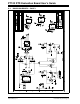
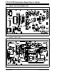
When connecting an external PT100 RTD, connect JP2 to External Position.
FIGURE 2-5: External RTD Connections.
V
REF
RTD (100Ω @°C)
V
DD
3
SPI
7kΩ
10 kΩ Digital
Potentiometer
PNP Transistor
MCP6022
1kΩ
RTD
R
WIRE
L
WIRE
RTD
R
WIRE
L
WIRE
RTD
R
WIRE
L
WIRE
2-wire RTD 4-wire RTD3-wire RTD