PT100 RTD Evaluation Board User’s Guide © 2007 Microchip Technology Inc.
Note the following details of the code protection feature on Microchip devices: • Microchip products meet the specification contained in their particular Microchip Data Sheet. • Microchip believes that its family of products is one of the most secure families of its kind on the market today, when used in the intended manner and under normal conditions. • There are dishonest and possibly illegal methods used to breach the code protection feature.
PT100 RTD EVALUATION BOARD USER’S GUIDE Table of Contents Preface ........................................................................................................................... 1 Introduction............................................................................................................ 1 Document Layout .................................................................................................. 1 Conventions Used in this Guide .................................................
PT100 RTD Evaluation Board User’s Guide NOTES: DS51607B-page iv © 2007 Microchip Technology Inc.
PT100 RTD EVALUATION BOARD USER’S GUIDE Preface NOTICE TO CUSTOMERS All documentation becomes dated, and this manual is no exception. Microchip tools and documentation are constantly evolving to meet customer needs, so some actual dialogs and/or tool descriptions may differ from those in this document. Please refer to our web site (www.microchip.com) to obtain the latest documentation available. Documents are identified with a “DS” number.
PT100 RTD Evaluation Board User’s Guide CONVENTIONS USED IN THIS GUIDE This manual uses the following documentation conventions: DOCUMENTATION CONVENTIONS Description Arial font: Italic characters Represents Referenced books Emphasized text A window A dialog A menu selection A field name in a window or dialog A menu path MPLAB® IDE User’s Guide ...is the only compiler...
Preface RECOMMENDED READING This user's guide describes how to use the PT100 RTD Evaluation Board. The following Microchip documents are available on our web site (www.microchip.com) and recommended as supplemental reference resources. MCP6S26 Data Sheet, “Single-Ended, Rail-toRail I/O, Low Gain PGA“ (DS21117) This data sheet provides detailed information regarding the MCP6S26 device.
PT100 RTD Evaluation Board User’s Guide CUSTOMER SUPPORT Users of Microchip products can receive assistance through several channels: • • • • • Distributor or Representative Local Sales Office Field Application Engineer (FAE) Technical Support Development Systems Information Line Customers should contact their distributor, representative or field application engineer for support. Local sales offices are also available to help customers.
PT100 RTD EVALUATION BOARD USER’S GUIDE Chapter 1. Product Overview 1.1 INTRODUCTION This chapter provides an overview of the PT100 RTD Evaluation Board and covers the following topics: • What is the PT100 RTD Evaluation Board? • What the PT100 RTD Evaluation Board kit includes. 1.2 WHAT IS THE PT100 RTD EVALUATION BOARD? The PT100 RTD Evaluation Board demonstrates how to bias a Resistive Temperature Detector (RTD) and accurately measure temperature. Up to two RTDs can be connected.
PT100 RTD Evaluation Board User’s Guide NOTES: DS51607B-page 6 © 2007 Microchip Technology Inc.
PT100 RTD EVALUATION BOARD USER’S GUIDE Chapter 2. Installation and Operation 2.1 INTRODUCTION The PT100 RTD Evaluation Board allows the user to evaluate Microchip’s solution to accurately measure temperature using RTD. When biasing RTDs to measure temperature, self-heat due to power dissipation has to be considered. RTD resistance availability typically ranges from 100Ω to 5,000Ω.
PT100 RTD Evaluation Board User’s Guide 2.3 GETTING STARTED This section describes how to quickly configure the PT100 RTD Evaluation Board. A simplified block diagram of the configuration is provided in Figure 2-1. PT100 RTD Evaluation Board PICmicro® Microcontroller CH0 USB PC FIGURE 2-1: RTD ADC Diff Amp CH1 RTD VREF PT100 RTD Evaluation Board Simplified Block Diagram. 2.3.1 Hardware Setup 1. Connect the USB cable to PC. 2.
Installation and Operation 2.3.2 Software Setup 1. Once the USB connection is secure, start the PT100RTD ThermalManagement.EXE file and select Enable Macro. When the software starts, the Configuration window will be displayed, as shown in Figure 2-3. FIGURE 2-3: PC Software GUI. 2. Select Enable/Disable for CH0 or CH1 (Channel 0 and Channel 1, respectively). 3. Select PGA gain, ADC sampling rate, and sampling buffer size for the stripchart display. 4.
PT100 RTD Evaluation Board User’s Guide 2.4 FUNCTIONAL DESCRIPTION 2.4.1 The PT100 RTD Evaluation Board The PT100 RTD Evaluation Board uses surface mount RTD to measure temperature. An external 2, 3, or 4-wire PT100 RTD can also be connected to measure temperature in remote locations. The RTDs are biased using a constant current source. In order to reduce self-heat due to power dissipation, the current magnitude is relatively low. The small voltage across the RTD is amplified using the MCP6S26 PGA.
Installation and Operation 2.4.1.2 RTD SIGNAL CHAIN The PGA is used to amplify the small voltage across the RTD. The reference input pin of the PGA is connected to the RTD negative terminal and Channel 0 and Channel 1 are connected to the positive terminals of each RTD. This allows only the voltage across the sensor to be amplified. The PGA has a gain error of ±1% (max.) for gains greater than 1 V/V. Refer to the datasheet (DS21685) for details.
PT100 RTD Evaluation Board User’s Guide NOTES: DS51607B-page 12 © 2007 Microchip Technology Inc.
PT100 RTD EVALUATION BOARD USER’S GUIDE Appendix A. Schematic and Layouts A.1 INTRODUCTION This appendix contains the following schematics and layouts for the PT100 RTD Evaluation Board: • • • • Board Schematic Board - Top Layer Board - Silk-screen Layer Board - Bottom Layer © 2007 Microchip Technology Inc.
PT100 RTD Evaluation Board User’s Guide BOARD SCHEMATIC - PAGE 1 DS51607B-page 14 1 2 M A.2 © 2007 Microchip Technology Inc.
Schematic and Layouts BOARD SCHEMATIC - PAGE 2 M A.3 © 2007 Microchip Technology Inc.
PT100 RTD Evaluation Board User’s Guide BOARD - TOP SILK-SCREEN LAYER : A.4 BOARD EDGE A.5 BOARD - TOP LAYER DS51607B-page 16 © 2007 Microchip Technology Inc.
Schematic and Layouts BOARD - BOTTOM SILK A.7 BOARD - BOTTOM LAYER : A.6 BOARD EDGE © 2007 Microchip Technology Inc.
PT100 RTD Evaluation Board User’s Guide NOTES: DS51607B-page 18 © 2007 Microchip Technology Inc.
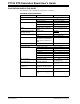
PT100 RTD EVALUATION BOARD USER’S GUIDE Appendix B. Bill Of Materials (BOM) TABLE B-1: Qty BILL OF MATERIALS Reference Description Manufacturer ® Part Number 10 C1, C2, C3, C4, CAP 1.0UF 10V CERAMIC X7R C5, C6, C12, 0805 C14, C15, C16 Kemet Electronics C0805C105K8RACTU 2 C7, C8 CAP 22PF 50V CERM CHIP 0805 SMD Panasonic® - ECG ECJ-2VC1H220J 1 C9 CAP CER 4700PF 100V X7R 10% 0805 TDK® Corporation C2012X7R2A472K 6 C10, C11, C18, CAP .
Bill Of Materials (BOM) TABLE B-1: Qty BILL OF MATERIALS (CONTINUED) Reference Description Manufacturer Part Number 1 R15 RES 35.7K OHM 1/8W 1% 0805 SMD Panasonic - ECG ERJ-6ENF3572V 3 R18, R22, R23 RES 1.00K OHM 1/10W 1% 0805 SMD Panasonic - ECG ERJ-6ENF1001V 2 R19, R21 RES 10.
Bill Of Materials (BOM) NOTES: © 2007 Microchip Technology Inc.
WORLDWIDE SALES AND SERVICE AMERICAS ASIA/PACIFIC ASIA/PACIFIC EUROPE Corporate Office 2355 West Chandler Blvd. Chandler, AZ 85224-6199 Tel: 480-792-7200 Fax: 480-792-7277 Technical Support: http://support.microchip.com Web Address: www.microchip.