
User manual


TC1303B DUAL-OUTPUT
REGULATOR USER’S GUIDE
© 2005 Microchip Technology Inc. DS51563A-page 1
Preface
INTRODUCTION
This chapter contains general information that will be useful to know before using the
TC1303B Dual-Output Regulator with Power-Good Output Demo Board. Items
discussed in this chapter include:
• Document Layout
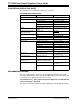
• Conventions Used in this Guide
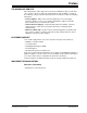
• Recommended Reading
• The Microchip Web Site
• Customer Support
• IDocument Revision History
DOCUMENT LAYOUT
This document describes how to use the TC1303B Dual-Output Regulator with
Power-Good Output Demo Board. The manual layout is as follows:
• Chapter 1. “Product Overview” – Important information about the TC1303B
Dual-Output Regulator with Power-Good Output Demo Board.
• Chapter 2. “Installation and Operation” – Provides a description of the demo
board and includes instructions on how to get started.
• Appendix A. “Schematic and Layouts” – Shows the schematic and layout
diagrams for the TC1303B Dual-Output Regulator with Power-Good Output Demo
Board.
• Appendix B. “Bill-Of-Materials (BOM)” – Lists the parts used to build the
TC1303B Dual-Output Regulator with Power-Good Output Demo Board.
NOTICE TO CUSTOMERS
All documentation becomes dated, and this manual is no exception. Microchip tools and
documentation are constantly evolving to meet customer needs, so some actual dialogs
and/or tool descriptions may differ from those in this document. Please refer to our web site
(www.microchip.com) to obtain the latest documentation available.
Documents are identified with a “DS” number. This number is located on the bottom of each
page, in front of the page number. The numbering convention for the DS number is
“DSXXXXXA”, where “XXXXX” is the document number and “A” is the revision level of the
document.