
User manual

8-Pin SOIC/MSOP/TSSOP/DIP Evaluation Board User’s Guide
DS51544A-page 18 © 2005 Microchip Technology Inc.
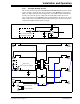
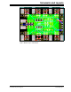
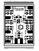
FIGURE 2-10: Op Amp Circuit #2 (MCP6021).
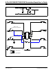
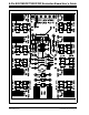
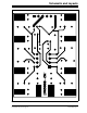
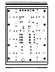
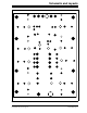
FIGURE 2-11: PCB Op Amp Circuit #2 (MCP6021).
R1C
3
2
6
4
7
+
–
R3C
R1B
R (P1)
2
4
3
1
6
5
7
8
U1
PAD7
PAD8
PAD5
PAD6
PAD1
R1B*
PAD2
R3C*
R1C*
PAD3
PAD4
C2
V
DD
V
SS
To power plane
To ground plane
V
SS
V
DD
C1
P1
Trace is cut,
resistor is installed
Trace is cut,
resistor is installed