
User manual

Installation and Operation
© 2005 Microchip Technology Inc. DS51544A-page 17
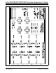
2.4.8 Example Op Amp Circuits
This section shows how the 8-Pin SOIC/MSOP/TSSOP/DIP Evaluation Board could be
used to evaluate op amp circuits. The first circuit is for the MCP601 and is shown in
Figure 2-8. Figure 2-9 shows which components on the PCB would be installed and
how the “unconnected” passive components would be jumpered into the circuit.
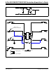
The second circuit is for the MCP6021 and is shown in Figure 2-10. Figure 2-11 shows
which components on the PCB would be installed and how the “unconnected” passive
components would be jumpered into the circuit.
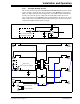
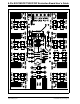
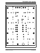
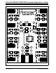
FIGURE 2-8: Op Amp Circuit #1 (MCP601).
FIGURE 2-9: PCB Connections for Op Amp Circuit #1 (MCP601).
C1C
C (P1)
R1C
3
2
6
4
7
+
–
R2
R2 is connected to pad 2
(not installed on PCB)
2
4
3
1
6
5
7
8
U1
PAD7
PAD8
PAD5
PAD6
PAD1
PAD2
C1C
PAD3
R1D
PAD4
C2
V
DD
V
SS
To power plane
To ground plane
V
SS
V
DD
C1
P1
R1C
Trace is cut,
resistor is installed
R2
External
to PCB