
User manual

8-Pin SOIC/MSOP/TSSOP/DIP Evaluation Board User’s Guide
DS51544A-page 16 © 2005 Microchip Technology Inc.
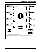
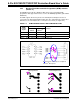
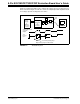
A typical system that would be used to evaluate the voltage supervisor/voltage detector
device is shown in Figure 2-7. This also shows an example input and output waveform
for a voltage supervisor/voltage detector device.
FIGURE 2-7: Evaluation System.
Variable
Voltage
R1
Test Point
Arbitrary Waveform
Generator
Output
Test
Point or
SOT-23-5/6 Evaluation Board PCB
C1
Supervisor
or
Voltage
Detector
Power
Supply
or
Arbitrary
Waveform
Device V
DD
out of valid operating range.
Oscilloscope
Output voltage may be indeterminate.
Generator
V
OUT
R2
R3
PCB
Pad