
User manual

Installation and Operation
© 2005 Microchip Technology Inc. DS51544A-page 15
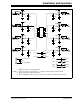
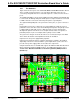
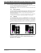
2.4.6 The PCB as a SOIC-8, MSOP-8, or TSSOP-8 to DIP-8 Socket
Converter
There may be occasions when it is desireable to convert the footprint of the device to
that of a DIP package. This allows the device to be installed into an exsisting DIP
socket. Two 1x4 row pins need to be installed into the PCB’s DIP footprint when the
device is installed into the appropriate package footprint.
This allows the PCB to convert the SOIC-8, MSOP-8 or TSSOP-8 footprints to a
300-mil DIP-8 footprint.
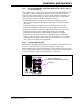
2.4.7 Evaluating a Voltage Supervisor or Voltage Detector Device
2.4.7.1 VOLTAGE SUPERVISORS
The following voltage supervisor is supported by this evaluation board.
TABLE 2-3: 8-PIN VOLTAGE SUPERVISOR
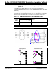
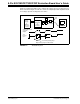
2.4.7.2 TESTING THE VOLTAGE SUPERVISORS TRIP POINT OPERATION
When evaluating a voltage supervisor/voltage detector device, a minimum set of test
equipment should be available. Table 2-4 shows the recommended test equipment.
TABLE 2-4: TEST EQUIPMENT
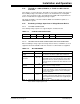
Device SOIC DIP MSOP TSSOP Comment
TC1232 Yes Yes — —
Hardware Connect to: Comment
Variable Power
Supply
V
DD
, V
SS
This allows the voltage to the SOT23 Evaluation Board
to be varied so the device output can be monitored.
Arbitrary Waveform
Generator
V
DD
, V
SS
This is similar to a variable power supply, but allows pro-
grammability into the input signal that the device will be
subjected to. This also allows a particular waveform to
be repeated (such as a 60 Hz sine wave that varies from
1V to 5V).
Digital Multi-Meter
(D.M.M.)
V
OUT
(1)
Used to indicate the output state (low or high) of the
voltage supervisor/voltage detector.
Oscilloscope V
OUT
(1)
Allows the device conditions and response to be evalu-
ated due to the ability to capture this information. This is
useful for faster signals and cases where small spikes
need to be detected.
Test Light (LED) V
OUT
(1)
Used to visually indicate the output state (low or high) of
the voltage supervisor/voltage detector. Ensure that the
current requirements of this LED can be supplied by the
device’s output pin.
Note 1: The pad connection to connect to the V
OUT
or RST pin will be dependent on the
device and the footprint option used.