
User manual

8-Pin SOIC/MSOP/TSSOP/DIP Evaluation Board User’s Guide
DS51544A-page 14 © 2005 Microchip Technology Inc.
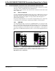
2.4.5 Baseline Flash Microcontroller Programmer (BFMP) Interface
(Header J1)
The BFMP interface allows a PICmicro MCU device to be programmed with
programmers that support this interface, such as the BFMP programmer (part number
PG164101).
The PCB supports two device pinouts. The default pinout already has the traces
connected to the appropriate PICmicro MCU pins. The optional pinout requires three
PCB traces to be cut and then three connections to be made (see Figure 2-5).
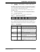
TABLE 2-2: BFMP HEADER SIGNALS AND PICMICRO MCU PINS
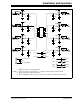
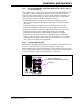
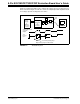
FIGURE 2-5: BFMP Header and Connections
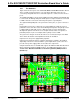
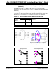
FIGURE 2-6: PCB Traces (Top and Bottom Layers).
BFMP
Header
Signal
Pin Number
Comment
Default
Pinout
Optional
Pinout
(1)
CLK 6 4 ICSP™ Clock
DT 7 5 ICSP Data
VPP 4 8
Note 1: Requires PCB traces to be cut and then jumpered.
Required “Cuts” and “Jumpers” for Optional
PICmicro
®
MCU pinout
Top-Layer Traces
Bottom-Layer Traces