
User manual

Installation and Operation
© 2005 Microchip Technology Inc. DS51544A-page 13
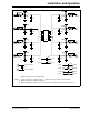
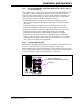
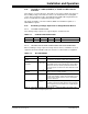
2.4.3 Passive Components (R1X, R2X, R3X, C1X, R1, R2, C1, C2, C3,
P1, P2, P3 and P4)
The footprints for these components are present to allow maximum flexibility in the use
of this PCB to evaluate a wide range of SOT-23-3 devices. The purpose of these
components may vary depending on the device under evaluation and how it is to be
used in the desired circuit. Refer to the device data sheet for the recommended
components that should be used when evaluating that device.
• Component R1X allows an in-line resistor that can be installed between the
device pin and the PCB pad. This may be required when interfacing this PCB to
other circuits
• Component R2X allows a pull-up resistor to be installed for the device pin
• Component R3X allows a pull-down resistor to be installed for the device pin
• Component C1X allows a capacitive load/filter to be installed for the device pin
• Component C1 allows a power supply filtering capacitor to be installed
• Components C2 and C3 allows a device filtering capacitor to be installed
• Components P1, P2, P3, and P4 are not connected and give a footprint (805
surface-mount) for a passive component (resistor, capacitor, etc.) to be installed
and jumpered into the PCB circuit. This allows for the evaluation of some simple
device circuits to be implemented on this PCB
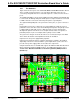
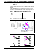
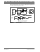
2.4.4 Installing Resistor R1X
Resistor R1X is shorted by default. Therefore, if resistor R1X is to be installed, the trace
across the component must be cut before it is installed (see Figure 2-4).
While evaluating a device, it may be desireable to see the signals on both sides of this
resistor. A test point is available so that both signals may be monitored. This test point
is the avenue between components R3X and C1X (see Figure 2-4).
FIGURE 2-4: Test point when resistor R1X is installed.
This trace must be cut
before resistor R1X can be installed
Test point