
User manual

Installation and Operation
© 2005 Microchip Technology Inc. DS51544A-page 9
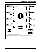
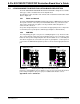
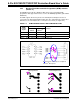
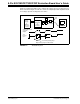
FIGURE 2-1: 8-Pin SOIC/MSOP/TSSOP/DIP Evaluation Board Circuit.
2
4
3
1
6
5
7
8
C1G*
R2G*
R3G*
R1G*
(3)
UX
C1H*
R2H*
R3H*
R1H*
(3)
PAD7
PAD8
C1E*
R2E*
R3E*
R1E*
(3)
C1F*
R2F*
R3F*
R1F*
(3)
PAD5
PAD6
C1A*
R2A*
R3A*
R1A*
(3)
PAD1
C1B*
R2B*
R3B*
R1B*
(3)
PAD2
C1C*
R2C*
R3C*
R1C*
(3)
PAD3
C1D*
R2D*
R3D*
R1D*
(3)
PAD4
C2
(2)
V
DD
V
SS
To power plane
To ground plane
V
SS
V
DD
C3
(2)
V
DD
V
SS
C1
(2)
P1
(1)
TP11
TP12
P2
(1)
TP13
TP14
P3
(1)
TP15
TP16
P4
(1)
TP17
TP18
* Optional components, circuit-dependent.
Note 1: Can be any passive component (R, C, ...) that fits onto a 805 surface-mount footprint.
2: Optional power/device filtering capacitors.
3: When installing this component, ensure to cut the trace between the two pads of the device.